


6
The electronic defrost timer sequence is enabled when the T1 input
on the board is energized. The timer starts only when the defrost
thermostat is closed and the contactor is energized.
Defrost mode is identical to cooling mode except that outdoor fan
motor stops and second--stage heat is turned on to continue
warming conditioned spaces.
To initiate defrost, the defrost thermostat must be closed. This can
be accomplished as follows:
1. Turn off power to outdoor unit.
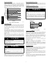
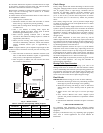
2. Disconnect outdoor fan motor lead from OF2 on control
board, see Fig. 9. Tape lead to prevent grounding.
3. Restart unit in heating mode, allowing frost to accumulate
on outdoor coil.
4. After a few minutes in heating mode, liquid line
temperature should drop below closing point of defrost
thermostat (approximately 30°F/--1.11°C).
5. Short between speedup term inals with a flat--blade
screwdriver. This reduces the timing sequence to 1/256th of
original time. (See Table 4.)
6. When you hear reversing valve change position, remove
screwdriver immediately; otherwise, control will terminate
normal 10--minute defrost cycle in approximately 2
seconds.
NOTE: Length of defrost cycle is dependent upon length of time
it takes to remove screwdriver from test pins after reversing valve
has shifted.
7. Unit will remain in defrost for r emainder of defrost cycle
time or until defrost thermostat reopens at approximately
65°F (18.33°C) coil temperature of liquid line.
8. Turn off power to outdoor unit and reconnect fan motor
lead to OF2 on control board.
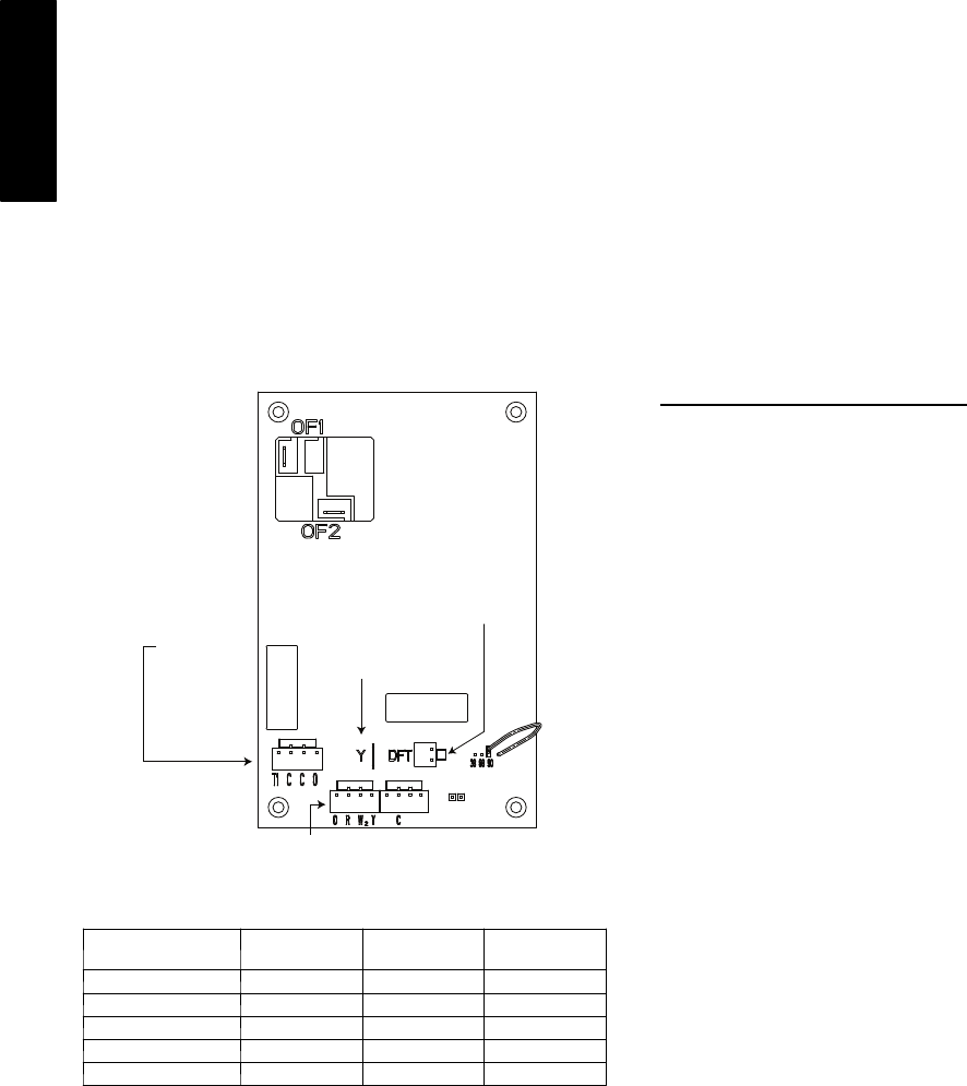
OUTDOOR FAN
RELAY
Y OUTPUT TO PRESSURE
SWITCHES AND CONTACTOR
THERMOSTAT INPUTS
T1 - ENABLES DEFROST
TIMER.MUST BE
ENERGIZED FOR
DEFROST TIMER
TO START
C - COMMON
O - REVERSING VALVE
SPEEDUP
HK32EA001
DEFROST THERMOSTAT
MUST BE CLOSED BEFORE
DEFROST TIMER BEGINS
A05332
Fig. 9 -- Defrost Control
Table 3 – Defrost Control Speedup--Timing Sequence
PARAMETER
MINIMUM
(MINUTES)
MAXIMUM
(MINUTES)
SPEEDUP
(NOMINAL)
30 --- min ute c yc le 27 33 7sec
50 --- min ute c yc le 45 55 12 sec
90 --- min ute c yc le 81 99 21 sec
10 --- min ute c yc le 9 11 2sec
5 m inutes 4.5 5.5 1sec
Check Charge
Factory charge amount and desired subcooling are shown on unit
rating plate. Charging method is shown on information plate inside
unit. To properly check or adjust charge, conditions must be
favorable for subcooling charging. Favorable conditions exist
when the outdoor temperature is between 70_F and 100_F
(21.11_C and 37.78_C), and the indoor temperature is between
70_F and 80_F (21.11_C and 26.67_C). Follow the procedure
below:
Unit is factory charged for 15ft (4.57 m) of lineset. Adjust charge
by adding or removing 0.6 oz/ft of 3/8 liquid line above or below
15ft (4.57 m) respectively.
For standard refrigerant line lengths (80 ft/24.38 m or less), allow
system to operate in cooling mode at least 15 minutes. If conditions
are favorable, check system charge by subcooling method. If any
adjustment is necessary, adjust charge slowly and allow system to
operate for 15 minutes to stabilize before declaring a properly
charged system.
If the indoor temperature is above 80_F (26.67_C), and the
outdoor temperature is in the favorable range, adjust system charge
by weight based on line length and allow the indoor temperature to
drop to 80_F (26.67_C) before attempting to check system charge
by subcooling method as described above.
If the indoor temperature is below 70_F (21.11_C), or the outdoor
temperature is not in the favorable range, adjust charge for line set
length above or below 15ft (4.57 m) only. Charge level should then
be appropriate for the system to achieve rated capacity. The charge
level could then be checked at another time when the both indoor
and outdoor temperatures are in a more favorable range.
NOTE: If line length is beyond 80 ft (24.38 m) or greater than 20
ft (6.10 m) vertical separation, See Long Line Guideline for
special char ging requirements.
Heating Check Chart Procedure
To check system operation during heating cycle, refer to the
Heating Check Chart on outdoor unit. This chart indicates whether
a correct relationship exists between system operating pressure and
air temperature entering indoor and outdoor units. If pressure and
temperature do not match on chart, system refrigerant charge may
not be correct. Do not use chart to adjust refrigerant charge.
Final Checks
IMPORTANT: Before leaving job, be sure to do the following:
1. Ensure that all wiring is routed away from tubing and sheet
metal edges to prevent rub--through or wire pinching.
2. Ensure that all wiring and tubing is secure in unit before
adding panels and covers. Securely fasten all panels and
covers.
3. Tighten service valve stem caps to 1/12--turn past finger
tight.
4. Leave Owner’s Manual with owner. Explain system
operation and periodic maintenance requirements outlined
in manual.
5. Fill out Dealer Installation Checklist and place in customer
file.
CARE AND MAINTENANCE
For continuing high performance and to minimize possible
equipment failure, periodic maintenance must be performed on this
equipment.
Frequency of maintenance may vary depending upon geographic
areas, such as coastal applications. See Users Manual for
information.
25HBB