


5
Install Electrical Accessories
Refer to the individual instructions packaged with kits or
accessories when installing.
Start--Up
CAUTION
!
PERSONAL INJURY HAZARD
Failure to follow this caution may result in personal
injury .
Wear safety glasses, protective clothing, and gloves when
handling refrigerant and observe the following:
S Front seating service valves are equipped with Schrader valves.
CAUTION
!
ENVIRONMENTAL HAZARD
Failure to follow this caution may result in environmental
damage.
Federal regulations require that you do not vent refrigerant to
the atmosphere. Recover during system repair or final unit
disposal.
CAUTION
!
UNIT OPERATION AND SAFETY HAZARD
Failure to follow this caution may result in personal injury,
equipment damage or improper operation.
S Do not overcharge system with refrigerant.
S Do not operate unit in a vacuum or at negative pressure.
S Do not disable low pressure switch in scroll compressor
applications.
S Compressor dome temperatures may be hot.
Follow these steps to properly start up system:
1. After system is evacuated, fully open liquid and vapor
service valves.
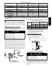
2. Unit is shipped with valve s tem(s) front seated (closed) and
caps installed. Replace stem caps after system is opened to
refrigerant flow (back seated). Replace caps finger--tight and
tighten with wrench an additional 1/12 turn.
3. Close electrical disconnects to energize system.
4. Set room thermostat at desired temperature. Be sure set
point is below indoor ambient temperature.
5. Set room thermostat to HEAT or COOL and fan control to
ON or AUTO mode, as desired. Operate unit for 15
minutes. Check system refrigerant charge.
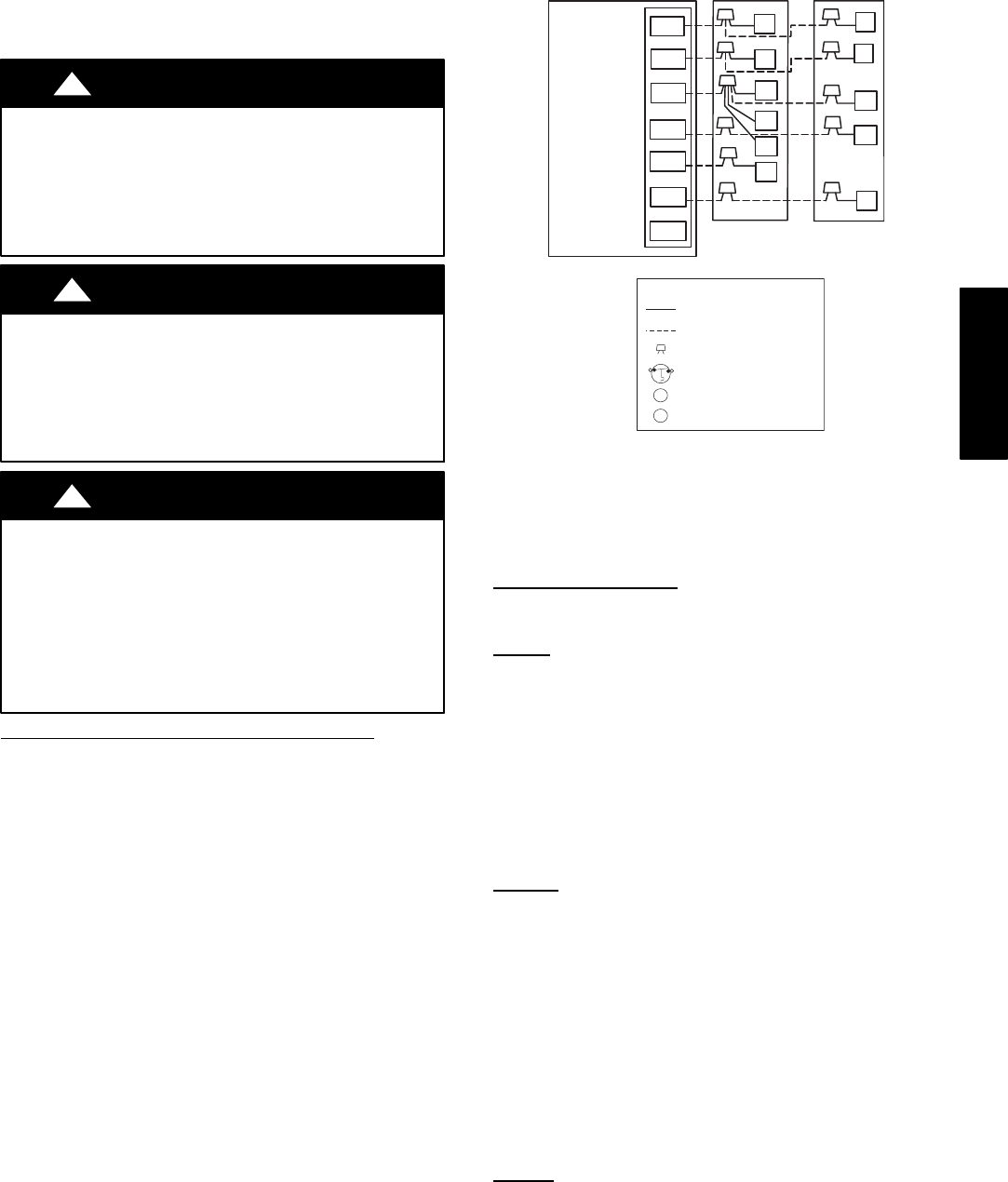
24 VAC HOT
R
C
W2
Y
G
R
C
RVS COOLING
C
W2
HP THERMOSTAT
TYPICAL
FAN COIL
HEAT
PUMP
G
O
E
W2
E
W3
R
Y
24 VAC COM
HEAT STAGE 2
COOL/HEAT
STAGE 1
INDOOR FAN
EMERGENCY
HEAT
O
*
*
*
IF AVAILABLE
*
LEGEND
24-V FACTORY WIRING
24-V FIELD WIRING
FIELD SPLICE CONNECTION
OUTDOOR THERMOSTAT
EMERGENCY HEAT RELAY
SUPPLEMENTAL HEAT RELAY
SHR
EHR
ODT
A02325 / A97413
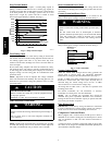
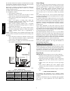
Fig. 8 -- Generic Wiring Diagrams
(See Thermostat Installation Instructions for specific unit com-
binations)
Sequence of Operation
Turn on power to indoor and outdoor units. Transformer is
energized.
Cooling
On a call for cooling, thermostat makes circuits R--O and R--Y, and
R--G. Circuit R--O ener gizes reversing valve, switching it to
cooling position. Circuit R --Y energizes contactor, starting outdoor
fan motor and compressor circuit. R--G energizes indoor unit
blower relay, starting indoor blower motor on high speed.
When thermostat is satisfied, its contacts open, de--energizing
contactor and blower relay. Compressor and motors should stop.
NOTE: If indoor unit is equipped with a time--delay relay circuit,
the indoor blower will run an additional 90 seconds to increase
system efficiency.
Heating
On a call for heating, thermostat makes circuits R--Y and R--G.
Circuit R--Y energizes contactor, starting outdoor fan motor and
compressor. Circuit R--G energizes indoor blower relay, starting
blower motor on high speed.
Should temperature continue to fall, R--W2 is made through
second--stage room thermostat. Circuit R--W2 energizes a relay ,
bringing on first bank of supplemental electric heat and providing
electrical potential to second heater relay (if used). If outdoor
temperature falls below setting of outdoor thermostat (field
installed option), contacts c lose to complete circuit and bring on
second bank of supplemental electric heat.
When thermostat is satisfied, its contacts open, de--energizing
contactor and relay. All heaters and motors should stop.
Defrost
The defrost control is a time/temperature control which includes a
field selectable (quick--connects located at board edge) time period
between defrost cycles (30, 60, or 90 minutes), factory set to 90
minutes.
25HBB