


3
Table 1 – Accessory Usage
Accessory
REQUIRED FOR LOW---AMBIENT
COOLING APPLICATIONS
(Below 55°F / 12.8°C)
REQUIRED FOR
LONG LINE APPLICATIONS*
(Over 80 ft. / 24.38 m)
REQUIRED FOR
SEA COAST APPLICATIONS
(Within 2 miles / 3.22 km)
Accumulator Standard Standard Standard
Ball Bearing Fan Motor Yes{ No No
Compressor Start Assist C apacitor and
Relay
Yes Yes No
Crankcase Heater Yes
Yes
No
Evaporator Freeze Thermostat Yes No No
Hard Shutoff TXV Yes Yes Yes
Isolation Relay Yes No No
Liquid Line Solenoid Valve No
See Long---Line Application
Guideline
No
Motor Master® Control or
Low Ambient Switch
Yes No No
Support Feet Recommended No Recommended
* For tubing lin e sets between 80 and 200 ft. (24.38 and 60.96 m) and/or 20 ft. (6.09 m) vertical differential, refer to Residential S plit---System Longline
Application Guideline.
{ Additional requirement for Low---Ambient Controller (full modulation feature) MotorMasterr Control.
Outdoor Unit Connected To Factory Approved Indoor
Unit
Outdoor unit contains correct system refrigerant charge for
operation with approved ARI rated indoor unit when connected by
15 ft (4.57 m) of field--supplied or factory--accessory tubing, and
factory s upplied filter drier. Check refrigerant charge for maximum
efficiency .
Refrigerant Tubing and Sweat Connections
Connect vapor tube to fitting on outdoor unit vapor service valves
(see Table 2). Connect liquid tubing to adapter tube on liquid
service valve. Use refrigerant grade tubing.
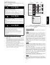
CAUTION
!
UNIT DAMAGE HAZARD
Failure to follow this caution may result in equipment
damage or improper operation.
Service valves must be wrapped in a heat--sinking material
such as a wet cloth while brazing.
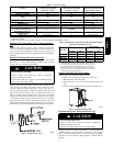
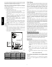
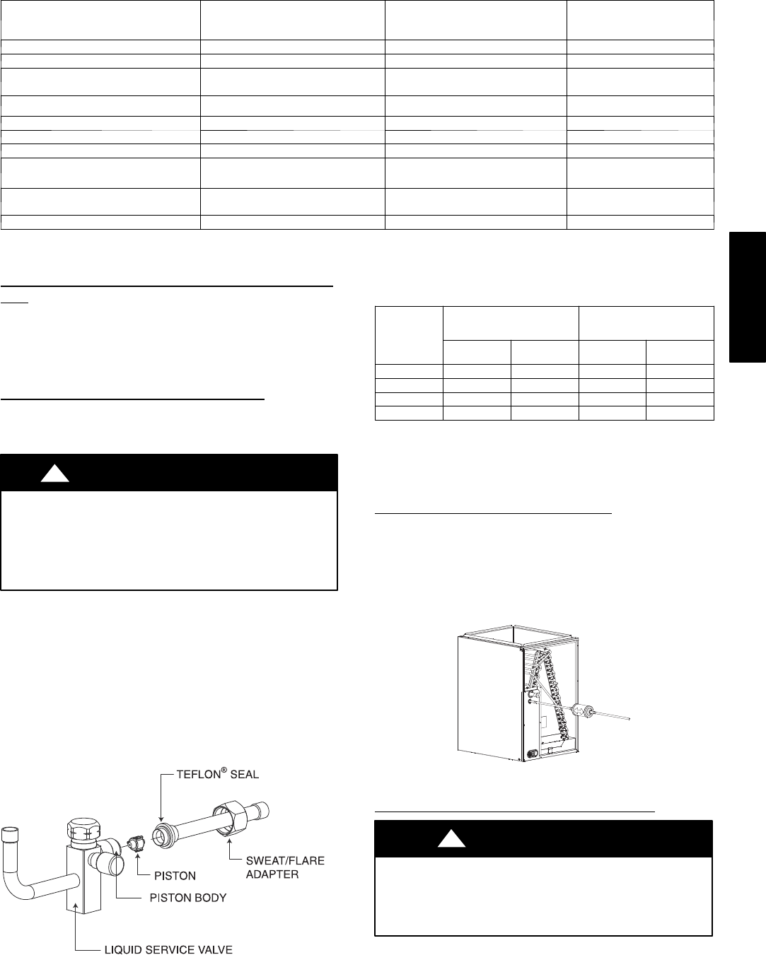
Remove plastic retainer holding outdoor piston in liquid service
valve, leaving the piston and piston retainer inside the valve.
Connect sweat/flare adapter provided, to valve. (See Fig. 4.)
Connect refrigerant tubing to fittings on outdoor unit vapor and
liquid service valves. Service valves are closed from factory and
ready for brazing. After wrapping service valve with a wet cloth,
tubing set can be brazed to service valve using either silver bearing
or non --silver bearing brazing material. Do not use soft solder
(materials which melt below 800°F/427°C). Consult local code
requirements. Refrigerant tubing and indoor coil are now ready for
leak testing. This check should include all field and factory joints.
A05226
Fig. 4 -- Liquid Service Valve
Table 2 – Refrigerant Connections and Recommended Liquid
and Vapor Tube Diameters (In.)
UNIT SIZE
LIQUID
RATED VAPOR
up to 80 ft. (24.38 m)*
Connection
Diameter
Tube
Diameter
Connection
Diameter
Tube
Diameter
018, 024 3/8 3/8 5/8 5/8
030, 036 3/8 3/8 3/4 3/4
042, 048 3/8 3/8 7/8 7/8
060 3/8 3/8 7/8 1--1/8
Notes:
1. Tube diametersare for total equivalent lengths up to 80 ft. (24.38 m)
2. Do no t apply capillary tube or f ixed orifice indoor coils to these units.
* ForTubingSet lengths between80 a nd 200 ft. (24.38 and 60.96 m)
horizontal or 20 ft. (6.10 m) vertical differential (250 ft./ 76.2 m)Total
Equivalent Length), refer to the Longline Guideline--- Air Conditioners
and Heat Pumps using Puronr Refrigerant.
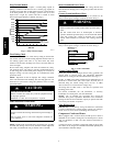
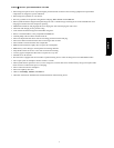
Install Liquid Line Filter Drier Indoor
Refer to Fig. 5 and install filter drier as follows:
1. Braze 5 in. (127 mm) liquid tube to the indoor coil.
2. W rap filter drier with damp cloth.
3. Braze filter drier to 5 in. (127 mm) long liquid t ube from
step 1.
4. Connect and braze liquid refrigerant tube to the filter drier .
A05227
Fig. 5 -- Liquid Line Filter Drier
Evacuate Refrigerant Tubing and Indoor Coil
CAUTION
!
UNIT DAMAGE HAZARD
Failure to follow this caution may result in equipment
damage or improper operation.
Never use the system compressor as a vacuum pump.
Refrigerant tubes and indoor coil should be evacuated using the
recommended deep vacuum method of 500 microns. The alternate
triple evacuation method may be used (see triple evacuation
procedure in service manual). Always break a vacuum with dry
nitrogen.
25HBB