


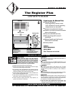
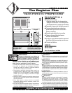
Installation
Instructions
PLACEMENT: For best results install The Register Plus on an inside wall. Headers and bracing are not
necessary. NOTE: The wall can must be installed in the TOP UP (horizontal) position only. Heater is not
approved for ceiling mount.
THERMOSTAT: A thermostat is required. A Cadet Elec tronic Thermostat is recommended for ultimate control
and comfort.
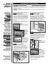
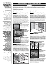
How do I install for new construction?
FIGURE 1
Metal legs position wall can
at minimum floor clearance.
The RM series REQUIRES A MINIMUM distance
of 6 inches from adjacent surfaces and 4½ inches
from the floor. However, Cadet RECOMMENDS
12 inches from all adjacent surfaces and 12 inches
from the floor (See Figure 5) for longer and cleaner
performance. Heaters must be spaced at least
3 feet apart.
Secure the wall can to the studs and/or sill plate
with screws through the larger (
3
/16 inch) holes.
(See Figures 1 and 2).
STEP 1
Mount Wall Can
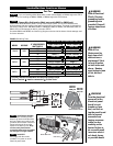
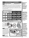
How do I install in an existing wall?
Route supply wire from circuit breaker to
thermo stat to wall can. Remove a knockout
and attach the supply wire with a strain relief
connector leaving 10 inches wire lead for later
use. Connect supply ground wire to grounding
pigtail in wall can (See Figure 4). Proceed to
PART TWO.
STEP 2
Route Supply Wires
Route supply wire from circuit breaker to wall
thermo stat, then to wall can. Remove a knockout
and attach the supply wire with a strain relief
connector leaving 10 inches wire lead for later
use (See Figure 4). Connect sup ply ground wire
to ground ing pigtail in wall can.
FIGURE 6
Insert wall can, legs
first, into opening
and rotate into wall.
FIGURE 7
Keeping front of
wall can flush with
finished surface,
secure to wall stud
with screws through
larger (
3
/16 inch) holes.
IMPORTANT: Insert two drywall screws into
the small holes opposite the wall stud into the
drywall to rest against backside of sheetrock
(keeping wall can flush to wall).
Proceed to PART TWO.
FIGURE 2
Bend one leg
90 degrees
for higher
placement
and secure
to studs.
FIGURE 3
Face of wall can must
extend ½ inch or
5
/8
inch from face of stud
to allow for thickness
of sheetrock. Mount
wall can flush with
finished surface.
FIGURE 4
KNOCK-OUT
(TWIST TO
REMOVE)
STRAIN RELIEF
CONNECTOR
GROUNDING
PIGTAIL
GROUNDING
WIRE
SUPPLY
WIRE
WIRE
CONNECTOR
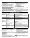
READ ALL
INSTRUCTIONS
AND SAFETY
INFORMATION
Part One
IMPORTANT!
It is extremely
important you
verify the
electrical supply
wires are the
same voltage as
the heater (i.e.
120 volt heater to
120 volt power
supply and 240 volt
heater to 240 volt
power supply).
If replacing an
existing heater,
check the labels
of the old heater
and replace using
the same voltage.
Hooking a 240 volt
heater to a 120 volt
power supply will
drastically reduce
the heater's
output. Hooking a
120 volt heater to a
240 volt power
supply will
destroy the heater.
Connecting your
heater to an
incompatible
power supply will
void the warranty.
Warranty is void if
any material is
sprayed on the
element or blower.
STEP 3
Mount Wall Can
STEP 2
Route Supply Wires
STEP 1
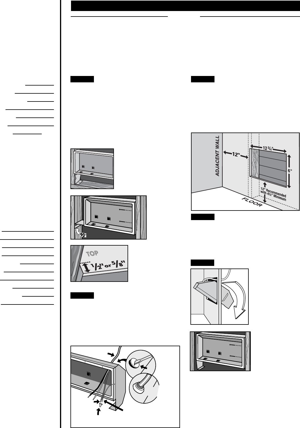
Cut Hole In Wall
FIGURE 5
Cut a hole 12¾ inches wide by 6 inches high
next to wall stud. The RM series REQUIRES A
MINIMUM distance of 6 inches from adjacent
surfaces and 4½ inches from the floor. However,
Cadet RECOMMENDS 12 inches from all adjacent
surfaces and 12 inches from the floor (See
Figure 5) for longer and cleaner performance.
Heaters must be spaced at least 3 feet apart.