


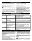
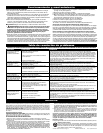
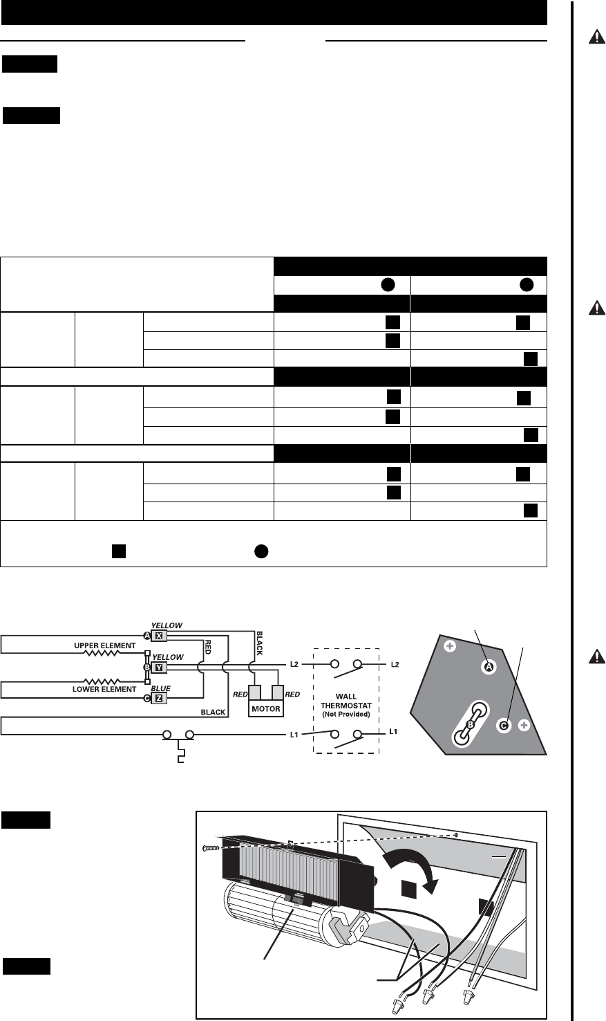
Element Wire Configuration (Multi-watt models RM151 or RM162 only)
Cadet’s Multi-Watt RM heater offers a variety of heat output options. You must first determine the
desired wattage and then configure the heating element wire connections. The heater is shipped from
the factory configured for 1600 Watts (240V) or 1200 Watts (208V) for RM162, and 1500 Watts (120V) for
RM151. If this is the wattage you desire, proceed to STEP 3.
On models RM151 and RM162, mark the wiring diagram on the back of the heater with the wattage used
for future reference.
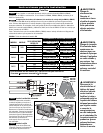
STEP 2
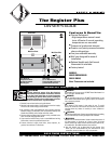
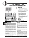
Installation
Instructions
Part Two
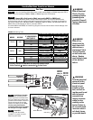
Fasten screw
Heater leads
Grounding
Pigtail
Blower wheel
Manual reset button
Supply leads
FIGURE 2
WARNING
Risk of Electrical
Shock. Connect
grounding lead to
grounding wire
provided. Keep all
foreign objects out
of heater.
WARNING
Risk of Fire.
Heater must be
kept clear of all
obstructions: a
minimum of 3 feet
in front; 6 inches
on both sides and
above. Heaters
must be kept clean
of lint, dirt and
debris.
WARNING
Turn the electrical
power off at the
electrical panel
board (circuit
breaker or fuse
box) and lock or
tag the panel board
door to prevent
someone from
turning on power
while you are
working on the
heater. Failure to
do so could result
in serious electri-
cal shock, burns,
or possible death.
If you are installing a Multi-Watt heater, model numbers RM151 or RM162, begin with STEP 2
below. If you are installing an RM202, RM208, or RM108, begin with STEP 3 below.
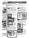
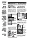
STEP 1
FIGURE 1 RM Wiring Table
Set the heater assembly (blower
wheel first) into the left side of the
wall can. Fasten at top with screw
provided. Unlace heater lead wires.
Connect the supply wires to the
heater wires (See Figure 2). Keep
all wires away from element
connections when wires are pushed
into free space on right of heater.
Secure grill with the screws
provided. Turn power on at the
electrical panel board.
STEP 3
STEP 4
Install Heater Assembly
Install Grill
MANUAL RESET
HIGH TEMP CUTOFF
VOLTAGEMODEL
240VRM162
208VRM162
IF YOUR DESIRED
WATTAGE IS:
1200
675
528
1600
900
700
YOUR WIRES WILL BE CONFIGURED LIKE THIS:
900W-240V
700W-240V
Upper Element A
675W-208V 525W-208V
Lower Element C
Yellow Terminal X
Yellow Terminal X
None (*)
Blue Terminal Z
None (*)
Yellow Terminal X
Blue Terminal Z
None (*)
Yellow Terminal X
Motor End View
Heater Element Locations
525W-208V
700W-240V
500W-120V
675W-208V
900W-240V
1000W-120V
Yellow Terminal X
Yellow Terminal X
None (*)
120VRM151
1500
1000
500
1000W-120V
500W-120V
Blue Terminal Z
None (*)
Yellow Terminal X
Yellow Terminal X
Yellow Terminal X
None (*)
*Cut Blue Terminal from Red Wire and wrap with electrical tape.
Yellow Terminal Y remains connected at B . Do Not Touch.