


12
DISCONNECT ELECTRICAL POWER
to the boiler and heating system before
servicing. Positively assure that no voltage is
present. Lock electrical boxes to prevent someone
from inadvertently restoring power before the
heating system is safe to operate.
NEVER DEFEAT OR JUMP OUT safety
devices.
PROTECT EACH BOILER circuit with a
properly sized over-current protection
device.
MAKE ELECTRICAL CONNECTIONS
CAREFULLY according to the boiler’s
wiring diagram and instructions
Refer to the Internal Wiring diagrams later in this
manual.
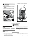
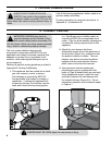
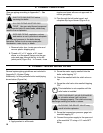
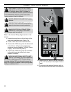
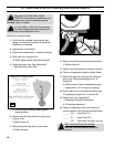
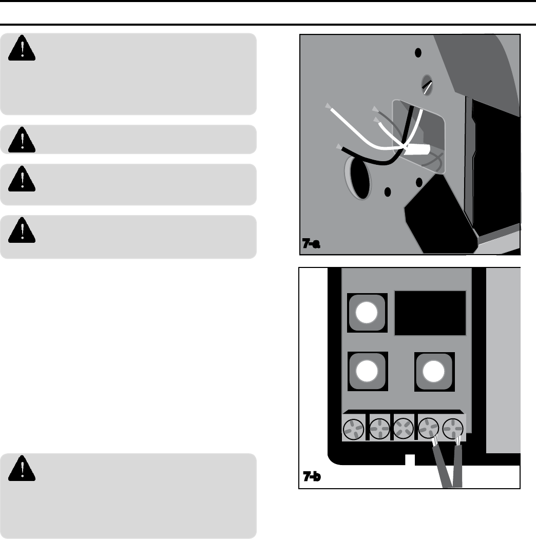
1. Locate the wiring box on the left side of the
boiler and open the cover (Figure 7-a).
2. Install a 120V disconnect near the boiler.
3. Connect the 120V wiring from the disconnect
to the boiler's white (neutral), black (hot),
and green (ground) labeled "120VAC Power
supply". Do not reverse polarity.
4. Connect the 120V wiring from the circulator
to the white (neutral) yellow (hot) wires
marked "circulator".
WIRE AN ADDITIONAL SAFETY LIMIT
such as a low water cutoff or temperature
limit device, other than an IQ™ Control device,
in series with the 120V circuit used to power the
boiler. Do not alter the boiler’s factory wiring when
adding an additional limit.
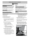
7. CONNECT ELECTRICAL WIRING
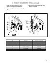
5. Connect the 24V wiring from the thermostat
to the "T-T" terminals on the Option Control
Panel.
6. To connect other external devices, refer to
the instructions included with these devices.
7-a
1
1
2
3 T
T
7-b