


10
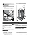
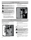
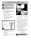
2. Screw the water supply manifold into the
boiler outlet tapping “O.”
3. Orient the manifold with the relief valve on
top.
4. Screw the relief valve into manifold tapping
“RV”.
i
This installation is not complete until the
relief valve is installed.
PIPE THE RELIEF VALVE DISCHARGE
to a location where it will not harm
people or damage property. The relief valve may
discharge scalding hot water or steam.
BLOCKING THE RELIEF VALVE may
result in boiler explosion.
5. Screw the temperature-pressure gage into
manifold tapping “G”.
6. Connect the system supply to the open end
of the manifold "S" using a 1¼” male NPT
tting.
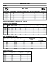
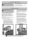
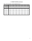
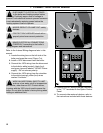
5. CONNECT GAS PIPING
Size gas piping according to Appendix C – Gas
Piping
SHUT OFF GAS SUPPLY before
servicing the boiler.
ALL GAS PIPING MUST BE GAS
TIGHT. Use gas rated thread compound
on all threaded joints to avoid leaks, which may
result in re or explosion.
SIZE GAS PIPING, regulators, valves,
and meters so as to provide an adequate
gas ow and pressure to the boiler during
operation. Failure to do so may cause poor
combustion, noise, injury, or death.
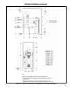
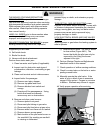
1. Remove boiler door, locate gas valve and
remove plastic shipping plug.
2. Thread a ¾" x 1½" nipple, a 90° street
elbow, or a Honeywell ange onto the gas
valve and pipe through the slot in the left
jacket panel (Figure 5-a). In Canada, close
nipples and street ells are not approved for
use as gas piping.
3. Pipe through the left jacket panel, and
complete drip leg as shown (Figure 5-a).
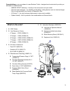
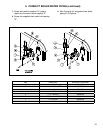
6. CONNECT BOILER WATER PIPING
General system piping guidelines are included in
Appendix D—System Piping.
Additionally, for this particular boiler install piping
shown below (Figure 6-a).
6-a
1. Apply sealant to all threads.
RV
S
R
O
G
D
5-a