


6
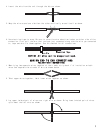
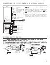
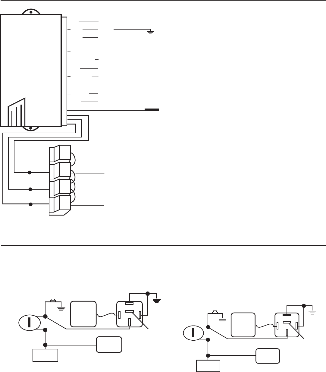
MECHANICAL NEUTRAL SAFETY SWITCH (Rear Wheel Drive Only)
When installing a Bulldog remote starter on GM vehicles or Dodge Dakotas built prior to 1996, you
must: Use the diagram below to create a circuit that will prevent the remote starter from starting
the vehicle unless the key is removed from the ignition switch.
PRE-1996 GM REAR WHEEL DRIVES WITH PURPLE CRANK WIRE – Optional part #775 required.
86
30
87a
87
85
5 Amp
fuse
Tie into
heavy white
wire on
4-relay
harness
(-) Negative
hood pin wire
Message
center or
key buzzer
Driver’s Door Switch
Key
Cylinder
TAN
GREEN
BLACK
YELLOW
BLUE
WHITE
NOT USED,
TAPE OFF
RED
Ground
Ground
86
30
87a
87
85
5 Amp
fuse
Tie into
heavy white
wire on
4-relay
harness
(-) Negative
hood pin wire
Message
center or
key buzzer
Driver’s Door Switch
Key
Cylinder
BLACK/LT.BLUE
LT.BLUE/GREEN
BLACK
YELLOW
BLUE
WHITE
RED
PRE-1996 DODGE DAKOTAS
Optional part #775 required.
NOT USED,
TAPE OFF
Ground
Ground
NEUTRAL SAFETY SWITCH
CONNECTING THE 11-PIN HARNESS & 4-RELAY HARNESS
CAUTION: Before connecting the 11-pin harness to
the module, double check all connections to be
sure they are secure and properly wrapped with
electrical tape. Plug the 11-pin harness into the
main control module. Connect the 3-pin harness
from the 4-relay harness to the module. NOTE: The
GRAY wire in the 11-pin harness will not be used.
Tape this wire up.
Press the start button, if your vehicle does not
start and run you may have a factory anti-thet
system. Refer to page 7 to see if this applies to
your vehicle.
RED
BLACK
BROWN
BLUE/BLACK
YELLOW/BLACK
BLUE
BLACK/BLUE
BLACK/WHITE
RED/BLACK
GRAY
To +12V constant
Ground
(-) Parking Light Output 250ma
(Requires optional part #775)
(+) Brake Switch
Ignition Input
(-) Aux. Alarm Channel Input
(-) To Hood Pin Switch
Tach to (-) Neg. Side of Coil
(-) Factory Alarm Shutdown
(Not Used)
WHT/BLK 16 ga.
WHITE 16 ga.
YEL/BLK 16 ga.
YELLOW ANTENNA
Keep as straight as
possible, tape end
to hold straight.
WHT/BLK 16 ga
YEL/BLK 16 ga
Tap here when
installing bypass
module 721.
WHITE 16 ga
For Passlock I
For Passlock I
For Passlock II
RED
3 Red wires need +12V
constant.
Either white wire to
Ignition 1. If your
car has 2 ignitions
use both.
To Starter/Crank Wire
To Heater/Blower
Motor Wire
RED
RED
WHITE
WHITE
YELLOW/BLACK
WHITE/BLACK
750ma (-)
Outputs