


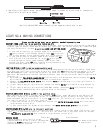
HEATER/BLOWER MOTOR WIRE(S) (+12V in run position only)
Most vehicles will have (1) blower wire; however some Fords, newer GM vehicles and Chrysler 94
and up will have (2) or more blower wires. To locate these wire(s) probe for wire(s) that only
show +12V when the ignition switch is in the RUN position. This wire(s) will not show +12V when
the ignition switch is in any other position.
1. If your vehicle has only (1) blower wire connect the WHITE WITH BLACK STRIPE wire from the 4-
relay harness to this wire.
2. If your vehicle has (2) blower wires, connect the WHITE WITH BLACK STRIPE wire to both.
STARTER/CRANK WIRE (+12V only in the start position)
The starter/crank wire is also in the main harness. Locate the wire that shows +12V on your test
light only in the cranking position. This wire will not show +12V in any other position. Attach
the YELLOW WITH BLACK STRIPE wire from the 4-relay harness to this wire.
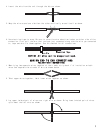
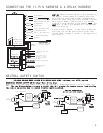
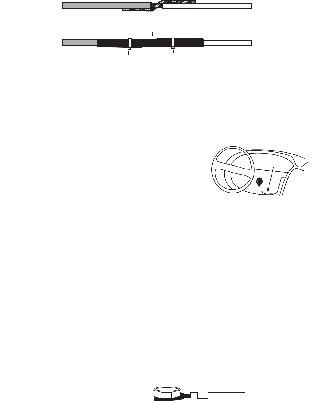
4. Use electrical tape to wrap, be sure to cover about 2 inches on either side of connection.
Secure with wire ties as shown.
Use this method ONLY when connecting two separate wires end to end.
Wire Tie
Electrical Tape
Wire Tie
LOCATING & MAKING CONNECTIONS
4
Note: Remove any paint below
the spade connector.
Factory Bolt
Spade Connector
Black Ground Wire
Please see the wiring chart on our website, www.bulldogsecurity.com.
CONSTANT POWER (+12V, key in any position including off)
These wire(s) are in your vehicle’s main ignition harness, usually located on the steering column coming
from the ignition switch. Probe each wire with your test light. The correct wire(s) will show +12V when
the ignition switch is in these 5 positions (ACC-LOCK-OFF-RUN-CRANK).
1. If your vehicle has only (1) constant power wire, attach the
RED wire from the 11-pin harness and both large RED wires from
the 4-relay harness to the constant power wire in the vehicle.
2. If your vehicle has (2) constant power wires, attach the RED
wire from the 11-pin harness and (1) large RED wire from the
4-relay harness to one of these constant power wires. Then
connect the other large RED wire from the 4-relay harness to the
second constant power wire in the vehicle.
IGNITION HARNESS
UNDER DASH
IGNITION WIRE(S) (+12V in run and crank position only)
The ignition wire(s) are also located in the main harness coming from the ignition switch. Probe each
wire with your test light, the correct wire(s) will show +12V only when the ignition switch is in the
RUN AND CRANK positions. The correct wires will not show +12V when in the OFF or ACCESSORY position.
Most Ford, GM, and Chrysler vehicles 1994 and up have at least (2) ignition wires. Most foreign vehicles
have only (1).
1. Strip back the YELLOW WITH BLACK STRIPE wire from the 11-pin harness and then strip back the WHITE
wire from the 4-relay harness and twist both of these wires together.
2. Connect the YELLOW WITH BLACK STRIPE wire and the WHITE wire from step (1) to the ignition wire in
the main harness.
3. If your vehicle has (2) ignition wires, connect the second WHITE wire from the 4-relay harness to
it.
4. If your vehicle has (3) ignition wires (some GMs) connect the second WHITE wire from the 4-relay
harnessto both the second and third ignition wires in the vehicle.
CHASSIS GROUND
Locate an easy to get to bolt or screw
located under the driver’s side of the dash and
attach the BLACK ground wire from the 11-pin
harness securely as pictured.