


Step (b): Calculate R of proposed system. 4” brick of C=1.25, therefore Rbrick = 1/C = 1/1.25
=0.80 1/8” mineral board of K = 0.29, therefore Rmin.bd. =1/029 x0.125 = 0.431
Step (c): Compare proposed system R of 1.231 to specified R of 0.893. Since proposed
system R is greater than required , the system is acceptable.
Definitions:
Install in accordance with 24 CFR, Part 3280 (HUD).
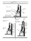
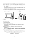
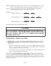
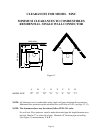
DETERMINING CHIMNEY LOCATION
A. CEILING EXIT ( Using 8” inch Diameter Residential Single Wall (minimum 24-ga.)
Black Chimney Connector
and any listed 2100 UL 103 HT type Chimney System ).
(See Page 14).
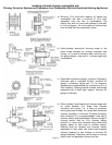
1. Suspend a plumb bob from ceiling above unit so that weight is hanging in center of
flue exit. (A small weight on a string will serve as a plumb bob). Mark ceiling where
string is suspended to locate center of chimney.
2. After locating center of hole, install ceiling support box, chimney flashing and rain
cap per chimney manufacturer’s instructions.
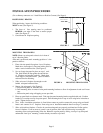
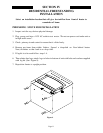
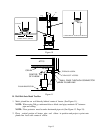
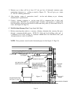
Now connect stove and ceiling support box using #24 ga. minimum blue or black steel
connector pipe (DO NOT USE GALVANIZED PIPE). Connect each section so crimped
end faces downward, and secure each section to each other using at least three (3) sheet
metal screws or rivets. Also use three (3) sheet metal screws to fasten pipe to collar on heater.
(See Figure 10. Page 15).
Thermal conductance = C =
Btu
=
W
(hr)(ft²)(°F) (m²)(°K)
Thermal conductance = K =
(Btu)(inch)
=
W
=
(Btu)
(hr)(ft²)(°F) (m)(°K) (hr)(ft)(°F)
Thermal conductance = R =
(ft²)(hr)(°F)
=
(m²)(°K)
Btu W
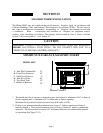
CAUTION
SPECIAL METHODS ARE REQUIRED WHEN PASSING THROUGH A
WALL OR CEILING. SEE INSTRUCTIONS AND BUILDING CODES.
“DO
NOT CONNECT THIS UNIT TO A CHIMNEY FLUE SERVING
ANOTHER APPLIANCE.”
Page 13