


20
wall (for aesthetic value only -- Equipment Control Module need not be
leveled for proper operation) and mark wall through 2 mounting holes.
2. Drill two 3/16--in. mounting holes in wall where marked. Thermostat may
be mounted to a standard junction box if desired. Hole pattern on Equip-
ment Control Module matches junction box mounting holes.
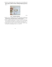
3. Secure rear plastic Equipment Control Module to wall with 2 screws and
anchors provided. Additional mounting holes are available for more se-
cure mounting if needed. Make sure all wires extend through hole in
Equipment Control Module.
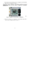
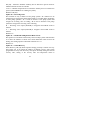
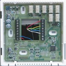
4. Adjust length and routing of each wire to reach proper connector block
and terminal on Equipment Control Module with 1/4-- in. extra length.
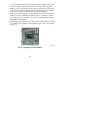
See Fig. 14.
A07219
Fig. 14 -- Equipment Control Module