14
12. WIRING DIAGRAMS
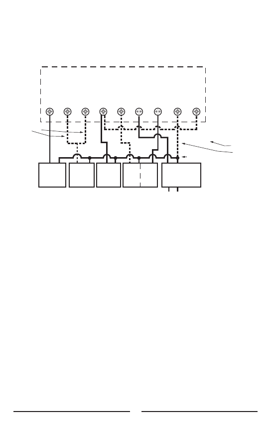
WIRING DIAGRAM NOTES
1. Dashed wires are optional.
2. If an "E" wire was connected to your old thermostat, it should be re-connected to the "E" terminal on
the new thermostat, and the optional jumper between "W" and "E" should not be used. Install this optional
jumper if you would like to use auxiliary heat as an emergency heat system.
3. Optional common wire to terminal "C" allows system power to power thermostat instead of batteries.
4. Use "B" or "O" wire but not both. Refer to equipment manufacturer's instructions to determine which
one to use.
5. If a "Y" and "C" wire are both present in your system, then "C" is the common wire.
6. Warning: If a "B" wire in you system is a common wire and you connect it to the "B" terminal instead of
"C", this may cause damage to you system.
7. Use terminal "Y2" only if you have a second compressor stage.
WARNING: THIS IS A LOW VOLTAGE THERMOSTAT (24 volts). A SERIOUS RISK OF FIRE EXISTS IF
YOU CONNECT THIS THERMOSTAT TO A LINE VOLTAGE APPLICATION (typically 115 or 230 volts). IF
UNCERTAIN ABOUT THE VOLTAGE CONSULT A PROFESSIONAL ELECTRICIAN.
G O B W Y2 R Y1 C E
TYPICAL PSPHA732
HEAT PUMP & AUX HEAT HOOKUP
AC LINE
FAN
REVERSING
VALVE
AUX
HEAT
COMP
STAGE
1
COMP
STAGE
2
XFMR
SYSTEM COMMON
NOTE 4
NOTE 7
NOTE 2
NOTE 3
OPTIONAL
JUMPER


