


4
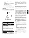
Table 2 – Accessory Usage
ACCESSORY
REQUIRED FOR LOW---AMBIENT
COOLING APPLICATIONS
(Below 55°F/12.8_C)
REQUIRED FOR LONG LINE
APPLICATIONS*
REQUIRED FOR
SEA COAST
APPLICATIONS
(Within 2 miles/3.22 km)
Ball Bearing Fan Motor Yes{ No No
Compressor Start Assist Capacitor and Relay Yes Yes No
Crankcase Heater Yes Yes No
Evaporator Freeze Thermostat Yes No No
H a rd S hu t --- O f f T X V Yes Yes Yes
Liquid Line Solenoid Valve No No No
Motor Master
®
or Low---ambient Pressure Switch Yes No No
Support Feet Recommended No Recommended
Winter Start Control Yes No No
* For tubing line sets between 80 and 200 ft. (24.38 and 60.96 m) and/or 35 ft. (10.7 m) vertical differential, refer to Residential Split---System Longline
Application Guideline.
{ Additional requirement for Low---Ambient Controller (full modulation feature) MotorMasterr Control.
Make Electrical Connections
Be sure field wiring complies with local and national fire, safety,
and electrical codes, and voltage to system is within limits shown
on unit rating plate. Contact local power company for correction of
improper voltage. See unit rating plate for recommended circuit
protection device.
NOTE: Operation of unit on improper line voltage constitutes
abuse and could af fect unit reliability. See unit rating plate. Do not
install unit in system where voltage may fluctuate above or below
permissible limits.
NOTE: Use copper wire only between disconnect switch and unit.
NOTE: Install branch circuit disconnect of adequate size per NEC
to handle unit starting current. Locate disconnect within sight from
and readily accessible from unit, per Section 440--14 of NEC.
Route Ground and Power Wires
Remove access panel to gain access to unit wiring. Extend wires
from disconnect through power wiring hole provided and into unit
control box.
!
WARNING
ELECTRICAL SHOCK HAZARD
Failure to follow this warning could result in personal injury or
death.
The unit cabinet must have an uninterrupted or unbroken
ground to minimize personal injury if an electrical fault should
occur. The ground may consist of electrical wire or metal
conduit when installed in accordance with existing electrical
codes.
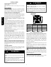
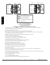
Connect Ground and Power Wires
Connect ground wire to ground connection in control box for
safety. Connect power wiring to contactor as shown in Fig. 5.
DISCONNECT
PER N.E.C. AND/OR
LOCAL CODES
CONTACTOR
GROUND
LUG
FIELD GROUND
WIRING
FIELD POWER
WIRING
BLUE
3 PHASE ONLY
A94025
Fig. 5 -- Line Connections
Connect Control Wiring
Route 24 --v control wires through control wiring grommet and
connect leads to control wiring (See Fig. 7). Refer to Installation
Instructions packaged with thermostat.
Use No. 18 AWG color--coded, insulated (35_C minimum) wire. If
thermostat is located more than 100 ft. (30.48 m) from unit, as
measured along the control voltage wires, use No. 16 AWG
color--coded wire to avoid excessive voltage drop.
All wiring must be NEC Class 1 and must be separated from
incoming power leads.
Use furnace transformer, fan coil transformer, or accessory
transformer for control power, 24v/40va minimum.
NOTE: Use of available 24v accessories may exceed the
minimum 40va power requirement. Determine total transformer
loading and increase the transformer capacity or split the load with
an accessory transformer as required.
Final Wiring Check
IMPORTANT: Check factory wiring and field wire connections
to ensure terminations are secured properly. Check wire routing t o
ensure wires are not in contact with tubing, sheet metal, etc.
CompressorCrankcaseHeater
When equipped with a crankcase heater , furnish power to heater a
minimum of 24 hr before starting unit. To furnish power to heater
only, set thermostat to OFF and close electrical disconnect to
outdoor unit.
A crankcase heater is required if refrigerant tubing is longer than
80 ft. (24.38 m). Refer to the Application Guideline and Service
Manual Longline Section--Residential Split--System Air
Conditioners and Heat Pumps.
Install Electrical Accessories
Refer to the individual instructions packaged with kits or
accessories when installing.
Start--Up
CAUTION
!
UNIT OPERATION AND SAFETY HAZARD
Failure to follow this caution may result in personal injury,
equipment damage or improper operation.
S Do not overcharge system with refrigerant.
S Do not operate unit in a vacuum or at negative pressure.
S Compressor dome temperatures may be hot.
CAUTION
!
PERSONAL INJURY HAZARD
Failure to follow this caution may result in personal injury.
Wear safety glasses, protective clothing, and gloves when
handling refrigerant and observe the following:
S Front seating service valves are equipped with Schrader
valves.
113A / 114A / 116B