


3
Sweat Connection
CAUTION
!
UNIT DAMAGE HAZARD
Failure to follow this caution may result in equipment
damage or improper operation.
Service valves must be wrapped in a heat--sinking material
such as a wet cloth while brazing.
Use refrigeration grade tubing. Service valves are closed from
factory and ready for brazing. After wrapping service valve with a
wet cloth, braze sweat connections using industry accepted
methods and materials. Consult local code requirements.
Refrigerant tubing and indoor coil are now ready for leak testing.
This check should include all field and factory joints.
Table 1 – Refrigerant Connections and Recommended Liquid
and Vapor Tube Diameters (In.)
113A
UNIT SIZE (SERIES)
LIQUID RATED VAPOR*
Connection
&Max.Tube
Diameter
Connection
Diameter
Tube
Diameter
018, 024 (Series C) 3/8 5/8 5/8
018, 024 (Series D) 3/8 3/4 3/4
030 3/8 3/4 3/4
036 (Series D) 3/8 3/4 3/4
036 (Series E) 3/8 7/8 7/8
042, 048 3/8 7/8 7/8
060 3/8 7/8 1 --- 1/8
114A
UNIT SIZE
LIQUID RATED VAPOR*
Connection
&Max.Tube
Diameter
Connection
Diameter
Tube
Diameter
018, 024 3/8 5/8 5/8
030, 036 3/8 3/4 3/4
042, 048, 049 3/8 7/8 7/8
060, 061 3/8 7/8 1 --- 1/8
116B
UNIT SIZE
LIQUID RATED VAPOR*
Connection
&Max.Tube
Diameter
Connection
Diameter
Tube
Diameter
018, 024 3/8 3/4 3/4
030 3/8 3/4 3/4
036 3/8 7/8 7/8
042, 048 3/8 7/8 7/8
060 3/8 7/8 1 --- 1/8
* Units are rated with 25 ft. (7.6 m) of lineset. See Product Data sheet for
performance data when using different size and length linesets.
Notes:
1. Do not apply capillary tube or fixed orifice indoor coils to these units.
2. For Tubing Set lengths between 80 and 200 ft. (24.38 an d 60.96 m)
horizontal or 35 ft. (10.7 m) vertical differential 250 ft. (76.2 m) Total
Equivalent Length), refer to the Residential Piping and Longline Guide
line--- Air Conditioners and Heat Pumps using Puron refrigerant.
3. For alternate liquid line options on 018 --- 042 size units, see Product
Data or Residential Piping and Application Guideline
Install Liquid--Line Filter Drier Indoor
CAUTION
!
UNIT DAMAGE HAZARD
Failure to follow this caution may result in equipment
damage or improper operation.
1. Installation of filter drier in liquid line is required.
2. Filter drier must be wrapped in a heat--sinking material
such as a wet cloth while brazing.
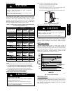
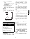
Refer to Fig. 3 and install filter drier as follows:
1. Braze 5-- in. liquid tube to the indoor coil.
2. Wrap filter drier with damp cloth.
3. Braze filter drier to above 5--in. (127 mm) liquid tube.
Flow arrow must point towards indoor coil.
4. Connect and braze liquid refrigerant tube to the filter drier.
A05178
Fig. 3 -- Liquid Line Filter Drier
Evacuate Refrigerant Tubi ng and Indoor Coil
CAUTION
!
UNIT DAMAGE HAZARD
Failure to follow this caution may result in equipment
damage or improper operation.
Never use the system compressor as a vacuum pump.
Refrigerant tubes and indoor coil should be evacuated using the
recommended deep vacuum method of 500 microns. The alternate
triple evacuation method may be used (see triple evacuation
procedure in service manual). Always break a vacuum with dry
nitrogen.
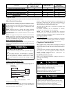
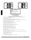
Deep Vacuum Method
The deep vacuum method requires a vacuum pump capable of
pulling a vacuum of 500 microns and a vacuum gage capable of
accurately measuring this vacuum depth. The deep vacuum method
is the most positive way of assuring a system is free of air and
liquid water. A tight dry system will hold a vacuum of 1000
microns after approximately 7 minutes. See Fig. 4.
500
MINUTES
01234567
1000
1500
LEAK IN
SYSTEM
VACUUM TIGHT
TOO WET
TIGHT
DRY SYSTEM
2000
MICRONS
2500
3000
3500
4000
4500
5000
A95424
A95424
Fig. 4 -- Deep Vacuum Graph
Final Tubi ng Check
IMPORTANT: Check to be certain factory tubing on both indoor
and outdoor unit has not shifted during shipment. Ensure tubes are
not rubbing against each other or any sheet metal or wires. Pay
close attention to feeder tubes, making sure wire ties on feeder
tubes are secure and tight.
113A / 114A / 116B