


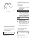
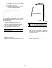

g. Manually close blower access panel door switch. Use a
piece of tape to hold switch closed.
WARNING: Blower access panel door switch opens
115-v power to control center. No component operation
can occur. Caution must be taken when manually closing
this switch for service purposes. Failure to follow this
warning could result in personal injury or death.
h. After fault code 11 flashes for at least 2 times, remove R,
W, and Y jumpers.
i. Turn setup switch SW-1 to OFF position.
j. Release blower access panel door switch and replace
blower access panel.
k. Operate furnace through 1 heat cycle to check for proper
operation and check LED status.
l. If furnace is operating properly and LEDs indicate proper
operation, replace main furnace door.
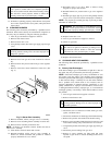
3. The control can also assist in troubleshooting by performing
a Component Test. The Component Test will functionally
operate all furnace components, except the gas valve.
a. To initiate Component Test proceed with the following:
(1.) Leave 115-v power to furnace turned on.
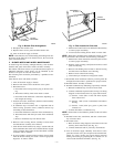
(2.) Remove main furnace door.
(3.) Remove blower access panel.
(4.) Turn setup switch SW-6 to ON position.
(5.) Manually close blower access panel door switch.
Use a piece of tape to hold switch closed.
WARNING: Blower access panel door switch opens
115-v power to control center. No component operation
can occur. Caution must be taken when manually closing
this switch for service purposes. Failure to follow this
warning could result in personal injury or death.
b. When items (1) through (5) above have been completed,
the following will occur:
(1.) The control center goes through a brief self test.
This self test takes approximately 2 sec to complete.
After door switch is closed, red (microprocessor)
LED briefly comes on. Then green LED comes on
for 1 sec, followed by 1 sec where both the green
and yellow LEDs are on. During this time, the
control is checking itself.
(2.) Inducer motor operates for 20 sec at low speed,
operates for 20 sec at high speed, then turns off.
(3.) Hot surface ignitor is energized for 15 sec, then
de-energized.
(4.) Main blower motor operates for 20 sec at low
speed, operates at high speed for 20 sec, then turns
off.
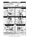
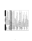
(5.) After component operation test is completed, 1 or
more fault codes (11, 22, 41, or 42) will flash. See
service label on back of main furnace door or Fig.
15 for explanation of codes.
NOTE: To repeat component test, turn setup switch SW-6 to OFF
and then back to ON.
c. After component test, perform the following:
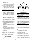
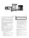
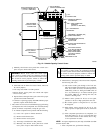
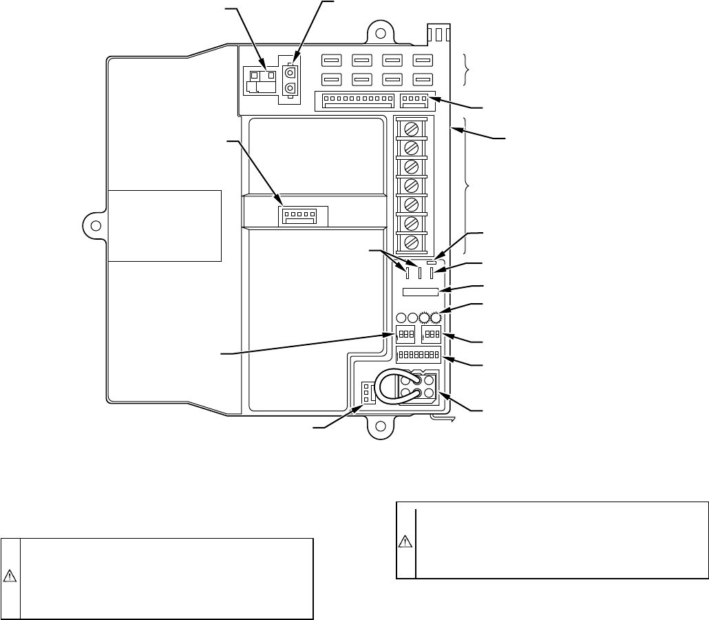
→ Fig. 12—Variable-Capacity Control Center
A98296
W2
COM
24V
W/W1 Y/Y2
RG
HUM
HOT SURFACE
IGNITOR CONNECTOR
EAC-ELECTRONIC AIR
CLEANER TERMINALS
(115-VAC 1 AMP MAX)
115-V
CONNECTORS
24-V THERMOSTAT
TERMINALS
PRESSURE SWITCH
CONNECTOR
HUM-HUMIDIFIER
TERMINAL
(24-VAC 0.5 AMP MAX)
TRANSFORMER
24-V CONNECTORS
3-AMP FUSE
STATUS AND DIAGNOSTIC
LED LIGHTS
AIR CONDITIONING
(A/C) SETUP SWITCH
SETUP SWITCHES
(SW) AND BLOWER
OFF DELAY SETUP
SWITCHES
MODEL PLUG
COMMUNICATION
CONNECTOR
CONTINUOUS
FAN (CF) SETUP
SWITCHES
MAIN BLOWER
CONTROL WIRE
CONNECTOR
DEHUMIDIFIER (DEHUM)
CONNECTOR
DEHUMIDIFY ENABLE (DE)
(WHEN PROVIDED)
—9—