


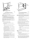
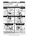
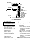
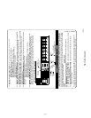
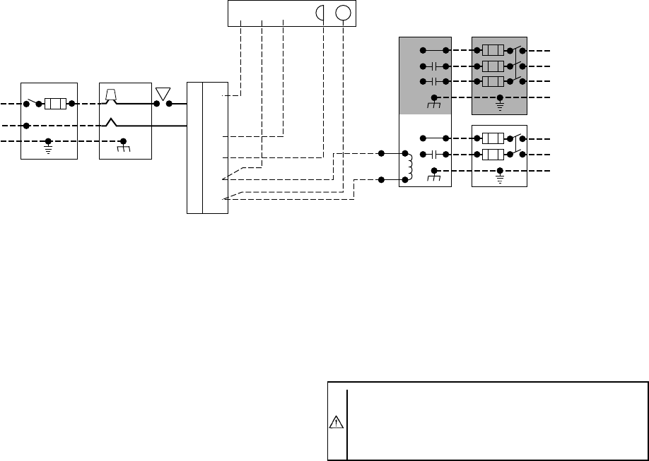
The 24-v circuit contains an automotive-type, 3-amp fuse located
on the control center. (See Fig. 12.) Any direct shorts of the 24-v
wiring during installation, service, or maintenance will cause this
fuse to blow. If fuse replacement is required, use ONLY a fuse of
identical size.
With power to the unit disconnected, check all electrical connec-
tions for tightness. Tighten all screws on electrical connections. If
any smoky or burned connections are found, disassemble the
connection, clean all parts, strip wire, and reassemble properly and
securely.
Reconnect electrical supply to unit and observe unit through 1
complete operating cycle. Electrical controls are difficult to check
without proper instrumentation; if there are any discrepancies in
the operating cycle, contact your dealer and request service.
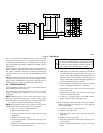
VIII. TROUBLESHOOTING
For an explanation of fault codes, refer to service label located on
back of main furnace door or Fig. 15.
The control center stores all fault codes for a period of 5 "good or
proper" operating cycles, regardless of 115- or 24-v power
interruption.
NOTE: Removing blower access panel opens blower access
panel door switch and terminates 115-v power to control center.
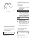
Look into blower access panel sight glass for current LED status.
1. To retrieve fault code proceed with the following:
NOTE: NO thermostat signal may be present at control center
and all blower time delay off periods must be completed.
a. Leave 115-v power to furnace turned on.
b. Remove main furnace door.
c. Look into blower access panel sight glass for current
LED status.
d. Remove blower access panel.
e. Turn setup switch SW-1 to ON position. (See Fig. 12 or
16 for location.)
f. Manually close blower access panel door switch. Use a
piece of tape to hold switch closed.
WARNING: Blower access panel door switch opens
115-v power to control center. No component operation
can occur. Caution must be taken when manually closing
this switch for service purposes. Failure to follow this
warning could result in personal injury or death.
g. LEDs display last fault code to occur first, followed by
any other fault that has occurred in the last 5 "good or
proper" cycles. The remaining faults displayed will be in
numerical order starting from the lowest number first.
Only 1 of each fault code will be displayed, regardless of
how many times the fault has occurred.
h. Fault code display will continue and repeat as described
above or until setup switch SW-1 is turned off.
i. Release blower access panel door switch and replace
blower access panel.
j. Operate furnace through 1 heat cycle to test for proper
operation and check LED status.
k. If furnace is operating properly and LEDs indicate
proper operation, replace main furnace door.
2. Fault code display can be removed from control’s display
mode by performing the following. This is also called the
"Clean Up Procedure."
a. Leave 115-v power to furnace turned on.
b. Remove main furnace door.
c. Look into blower access panel sight glass for current
LED status.
d. Remove blower access panel.
e. Turn setup switch SW-1 to ON position. (See Fig. 12 or
16 for location.)
f. Jumper thermostat terminals R, W, and Y on control
center.
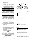
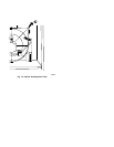
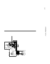
→ Fig. 11—Field Wiring
A98325