


61
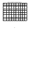
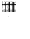
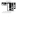
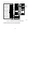
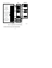
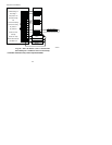
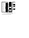
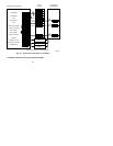
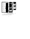
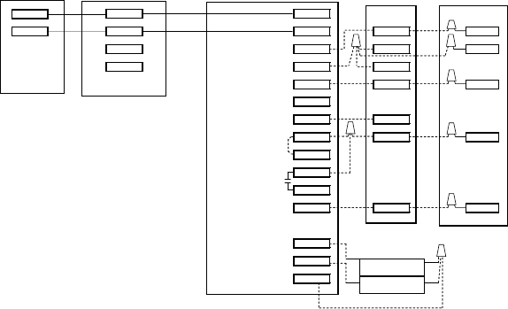
WIRING DIAGRAMS
Display module
Display module
wall mount
Equipment Control Module Fan Coil Heat Pump
V+ V+
Vg Vg O O
V+ RVS/Heat Stage 2 O/B W2 W3 W2
Vg Heat Stage 1 W/W1 W2
Compressor Y/Y2 Y Y
Y1 / W2
Fan G G
24VAC Hot Heating Rh R R
24VAC Hot Cooling Rc
Dry Contact 1 D1
Dry Contact 2 D2
24VAC Common C C C
Outdoor Air Temp OAT
Remote Room Sensor RRS
OAT/RRS Com SRTN
Outdoor Sensor *
Remote Room
Sensor *
V+
Vg
A08151
Fig. 17 -- Display to Equipment Control Module Connection
* Indicates connection may not be required/available.