


14
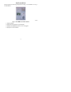
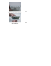
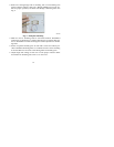
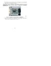
2. Route wires through large hole in mounting base. Level mounting base
against wall (for aesthetic value only—Display Module need not be lev-
eled for proper operation) and mark wall through 2 mounting holes. See
Fig. 6.
A07165
Fig. 6 -- Backplate Mounting
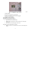
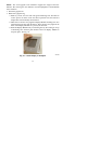
3. Drill two 3/16 --in. mounting holes in wall where marked. Thermidistat
Control may be mounted to a standard junction box, if desired. Hole pat-
tern on Thermidistat Control mounting base matches junction box mount-
ing holes.
4. Secure rear plastic mounting base to wall with 2 screws and anchors pro-
vided. Additional mounting holes are available for more secure mounting
if needed. Make sure all wires extend through hole in mounting base.
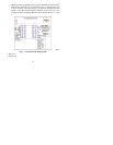
5. Adjust length a nd routing of each wire to reach proper connector block
and terminal on mounting base with 1/4--i n. extra wire.