


IX. INSTALL ELECTRICAL ACCESSORIES
Refer to the individual instructions packaged with kits or acces-
sories when installing.
X. START-UP
CAUTION: To prevent compressor damage or personal
injury, observe the following:
•Do not overcharge system with refrigerant.
•Do not operate unit in a vacuum or at negative pressure.
•Do not disable low-pressure switch.
In scroll-compressor applications:
•Dome temperatures may be hot.
•In 3-phase application, incorrect phasing will cause
reverse rotation, resulting in elevated noise levels, equal-
ized pressures, and reduced current draw. Correct by
reversing power connection L1 and L2 on contactor.
CAUTION: To prevent personal injury wear safety
glasses, protective clothing, and gloves when handling
refrigerant and observe the following:
•Back-seating service valves are not equipped with
Schrader valves. Fully back seat (counterclockwise)
valve stem before removing gage-port cap.
•Front-seating service valves are equipped with Schrader
valves.
CAUTION: Do not vent refrigerant to atmosphere. Re-
cover during system repair or final unit disposal.
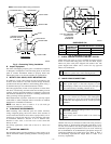
1. Fully back seat (open) liquid- and vapor-tube service
valves.
2. Unit is shipped with valve stem(s) front seated (closed) and
caps installed. Replace stem caps after system is opened to
refrigerant flow. Replace caps finger-tight and tighten with
wrench an additional 1/12 turn.
3. Close electrical disconnects to energize system.
4. Set room thermostat at desired temperature. Be sure set
point is below indoor ambient temperature.
5. Set room thermostat to COOL and fan control to ON or
AUTO mode, as desired. Operate unit for 15 minutes.
Check system-refrigerant charge.
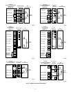
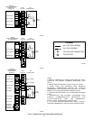
A. Sequence of Operation
Turn on power to indoor and outdoor units. Transformer is
energized.
On a call for cooling, thermostat makes circuits R-Y and R-G.
Circuit R-Y energizes contactor, starting outdoor-fan motor and
compressor circuit. R-G energizes indoor unit-blower relay, start-
ing indoor-blower motor on high speed.
When thermostat is satisfied, its contacts open, de-energizing
contactor and blower relay. Compressor and motors stop.
If indoor unit is equipped with a time-delay relay circuit, the
indoor blower will run an additional 90 sec to increase system
efficiency.
XI. CHECK CHARGE
A. Unit Charge
Factory charge is shown on unit-rating plate. Adjust charge by
following procedure shown on charging tables located on unit.
NOTE: If superheat- or subcooling-charging conditions are not
favorable, charge must be weighed in accordance with unit-rating
plate ± 0.6 oz/ft of 3/8-in. liquid line above or below 15 ft
respectively.
EXAMPLE:
25 ft – 15 ft = 10 ft X 0.6 oz/ft=6ozofadditional charge
B. Cooling Only Procedure
The following procedure is valid when indoor airflow is within ±
21 percent of its rated CFM.
1. Operate unit a minimum of 10 minutes before checking
charge.
2. Measure suction pressure by attaching a gage to suction-
valve service port.
3. Measure suction temperature by attaching an accurate
thermistor-type or electronic thermometer to suction line at
service valve.
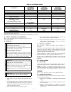
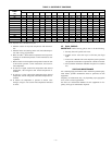
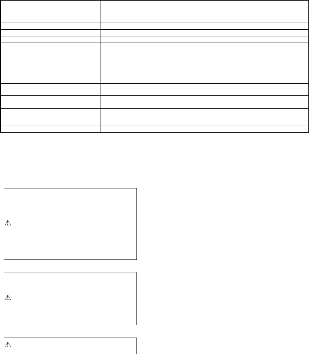
TABLE 2—ACCESSORY USAGE
ACCESSORY
REQUIRED FOR
LOW-AMBIENT
APPLICATIONS
(BELOW 55°F)
REQUIRED FOR
LONG-LINE
APPLICATIONS*
(OVER 50 FT)
REQUIRED FOR
SEA COAST
APPLICATIONS
(WITHIN 2 MILES)
Crankcase Heater Yes Yes No
Evaporator Freeze Thermostat Yes No No
Winter-Start Control Yes† No No
Accumulator No No No
Compressor Start-Assist
Capacitor and Relay
Yes Yes No
Low-Ambient Controller,
MotorMasterT Control,
or
Low-Ambient Pressure Switch
Yes No No
Wind Baffle
See Low-Ambient
Instructions
No No
Coastal Filter No No Yes
Support Feet Recommended No Recommended
Liquid-Line Solenoid Valve
or
Hard-Shutoff TXV
No
See Long-Line
Application
Guideline
No
Ball-Bearing Fan Motor Yes‡ No No
*For tubing-line sets between 50 and 175 ft, refer to Residential Split-System Long-Line Application Guideline.
†Only when low-pressure switch is used.
‡Required for Low-Ambient Controller (full-modulation feature) and MotorMasterT Control only.
—4—