


B. Inspect Equipment
File claim with shipping company prior to installation if shipment
is damaged or incomplete. Locate unit-rating plate on unit-corner
panel. It contains information needed to properly install unit.
Check rating plate to be sure unit matches job specifications.
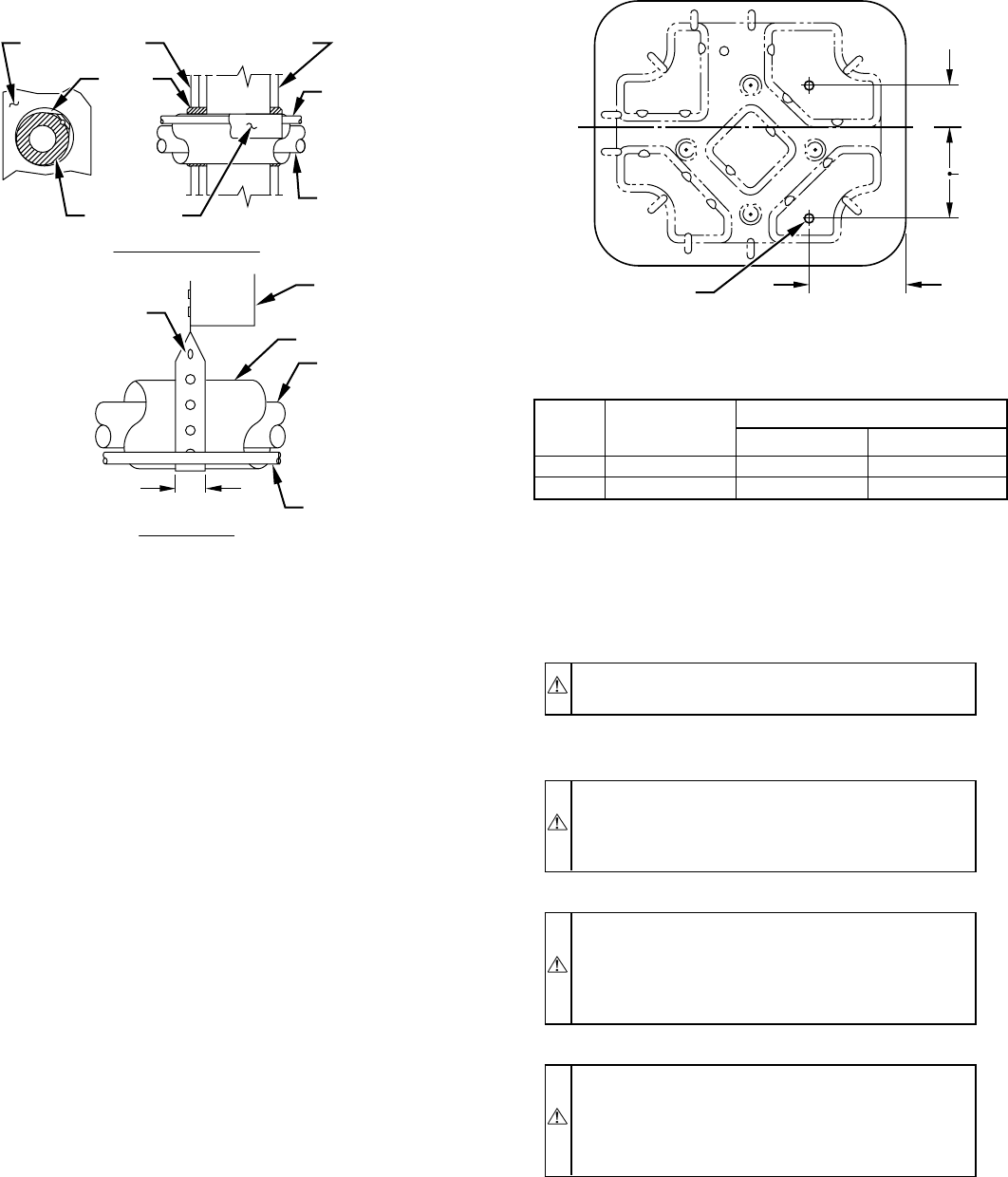
II. INSTALL ON A SOLID, LEVEL MOUNTING PAD
If conditions or local codes require the unit be attached to pad,
tie-down bolts should be used and fastened through knockouts
provided in unit base pan. Refer to unit-mounting pattern in Fig. 3
to determine base-pan size and knockout-hole location.
On rooftop applications, mount on level platform or frame. Place
unit above a load-bearing wall and isolate unit and tubing set from
structure. Arrange supporting members to adequately support unit
and minimize transmission of vibration to building. Consult local
codes governing rooftop applications.
Roof-mounted units exposed to winds above 5 mph may require
wind baffles to achieve adequate defrost. Consult Low-Ambient
Guideline for wind-baffle construction.
NOTE: Unit must be level to within ± 2° (± 3/8 in./ft) per
compressor manufacturer specifications.
III. CLEARANCE REQUIREMENTS
When installing, allow sufficient space for airflow clearance,
wiring, refrigerant piping, and service. Allow 30-in. clearance to
service end of unit and 48 in. above unit. For proper airflow, a 6-in.
clearance on 1 side of unit and 12 in. on all remaining sides must
be maintained. Maintain a distance of 24 in. between units.
Position so water, snow, or ice from roof or eaves cannot fall
directly on unit.
On rooftop applications, locate unit at least 6 in. above roof
surface.
IV. OPERATING AMBIENTS
The minimum outdoor-operating ambient in cooling mode is 55°F,
and the maximum outdoor-operating ambient in cooling mode is
125°F.
V. CHECK INDOOR CHECK-FLO-RATER™ PISTON
Check indoor-coil piston to see if it matches the required piston
shown on outdoor unit-rating plate. If it does not match, replace
indoor-coil piston with piston shipped with outdoor unit. The
piston shipped with outdoor unit is correct for any approved
indoor-coil combination.
CAUTION: Remove indoor-coil piston if unit is to be
installed on system with a TXV-metering device.
VI. MAKE PIPING CONNECTIONS
WARNING: Relieve pressure and recover all refrigerant
before system repair or final unit disposal to avoid
personal injury or death. Use all service ports and open all
flow-control devices, including solenoid valves.
CAUTION: If ANY refrigerant tubing is buried, pro-
vide a 6-in. vertical rise at service valve. Refrigerant-
tubing lengths up to 36 in. may be buried without further
consideration. For lengths above 36 in., consult your local
distributor.
CAUTION: To prevent damage to unit or service valves
observe the following:
•Use a brazing shield.
•Wrap service valves with wet cloth or use a heat sink
material.
Outdoor units may be connected to indoor unit using accessory-
tubing package or field-supplied refrigerant-grade tubing of cor-
rect size and condition. For tubing requirements beyond 50 ft,
substantial capacity and performance losses can occur. Following
the recommendations in the Residential Split-System Long-Line
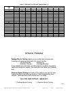
Application Guideline will reduce these losses. Refer to Table 1
for field-tubing equivalent-line length. Refer to Table 2 for
accessory requirements.
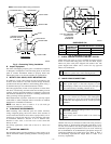
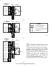
Fig. 2—Connecting Tubing Installation
A94028
INSULATION
VAPOR TUBE
LIQUID TUBE
OUTDOOR WALL INDOOR WALL
LIQUID TUBE
VAPOR TUBE
INSULATION
CAULK
Avoid contact between tubing and structureNOTE:
THROUGH THE WALL
HANGER STRAP
(AROUND VAPOR
TUBE ONLY)
JOIST
1″ MIN.
SUSPENSION
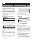
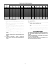
Fig. 3—Mounting Unit to Pad
DIMENSIONS (IN.)
UNIT
SIZE
MINIMUM
MOUNTING-PAD
DIMENSIONS
TIEDOWN KNOCKOUT LOCATIONS
AB
018 20 x 27 4–1/8 7–1/8
024–060 26 x 32 5–1/16 9-11/16
A97375
B
A
L
C
8
3
⁄16″
3
⁄8 IN. DIA TIEDOWN
KNOCKOUTS
(2) PLACES
IN BASEPAN
—2—