


For buried-line applications greater than 36 in., consult your local
distributor.
If refrigerant tubes or indoor coil are exposed to atmosphere, they
must be evacuated to 500 microns to eliminate contamination and
moisture in the system.
A. Outdoor Unit Connected to Factory-Approved In-
door Unit
Outdoor unit contains correct system-refrigerant charge for opera-
tion with indoor unit of same size when connected by 15 ft of
field-supplied or factory-accessory tubing. Check refrigerant
charge for maximum efficiency.
B. Refrigerant Tubing
Connect tubing to fittings on outdoor unit vapor- and liquid-
service valves. (See Table 1.) Use refrigerant-grade tubing.
C. Sweat Connection
CAUTION: To avoid valve damage while brazing, ser-
vice valves must be wrapped in a heat-sinking material,
such as a wet cloth.
Service valves are closed from factory and ready for brazing. After
wrapping service valve with a wet cloth, tubing set can be brazed
to service valve using either silver-bearing or non-silver-bearing
brazing material. Consult local code requirements. Refrigerant
tubing and indoor coil are now ready for leak testing. This check
should include all field and factory joints.
VII. MAKE ELECTRICAL CONNECTIONS
WARNING: To avoid personal injury or death, do not
supply power to unit with compressor terminal-box cover
removed.
Be sure field wiring complies with local and national fire, safety,
and electrical codes, and voltage to system is within limits shown
on unit-rating plate. Contact local power company for correction of
improper voltage. See unit-rating plate for recommended circuit-
protection device.
NOTE: Operation of unit on improper line voltage constitutes
abuse and could affect unit reliability. See unit-rating plate. Do not
install unit in system where voltage may fluctuate above or below
permissible limits.
NOTE: Use copper wire only between disconnect switch and
unit.
NOTE: Install branch-circuit disconnect of adequate size per
NEC to handle unit-starting current. Locate disconnect within sight
from and readily accessible from unit, per Section 440-14 of NEC.
A. Route Ground and Power Wires
Remove access panel to gain access to unit wiring. Extend wires
from disconnect through power wiring hole provided and into
unit-control box.
WARNING: The unit cabinet must have an uninter-
rupted or unbroken ground to minimize personal injury if
an electrical fault should occur. The ground may consist
of electrical wire or metal conduit when installed in
accordance with existing electrical codes. Failure to
follow this warning can result in an electric shock, fire, or
death.
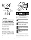
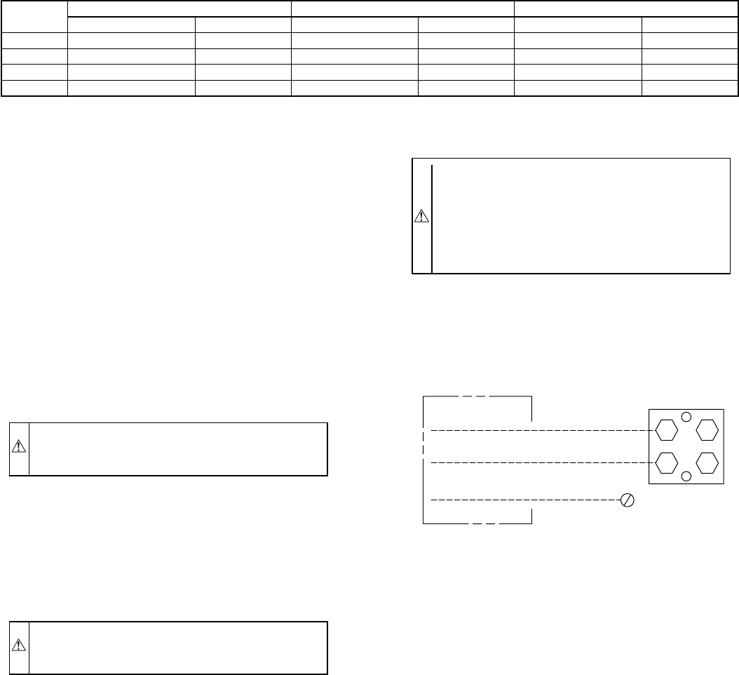
B. Connect Ground and Power Wires
Connect ground wire to ground connection in control box for
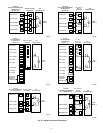
safety. Connect power wiring to contactor as shown in Fig. 4.
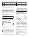
C. Connect Control Wiring
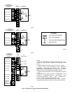
Route 24v control wires through control-wiring grommet and
connect leads to control wiring. (See Fig. 5.)
Use No. 18 AWG color-coded, insulated (35°C minimum) wire. If
thermostat is located more than 100 ft from unit, as measured
along the control-voltage wires, use No. 16 AWG color-coded
wire to avoid excessive voltage drop.
All wiring must be NEC Class 1 and must be separated from
incoming power leads.
Use furnace transformer, fan-coil transformer, or accessory trans-
former for control power, 24v/40va minimum.
NOTE: Use of available 24v accessories may exceed the mini-
mum 40va power requirement. Determine total transformer load-
ing and increase the transformer capacity or split the load with an
accessory transformer as required.
IMPORTANT: Check factory wiring and wire connections to
ensure terminations are secured properly. Check wire routing to
ensure wires are not in contact with tubing, sheet metal, etc.
VIII. COMPRESSOR CRANKCASE HEATER
When equipped with a crankcase heater, furnish power to heater a
minimum of 24 hr before starting unit. To furnish power to heater
only, set thermostat to OFF and close electrical disconnect to
outdoor unit.
A crankcase heater is required if refrigerant tubing is longer than
50 ft. Refer to Residential Split-System Long-Line Application
Guideline.
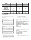
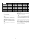
TABLE 1—REFRIGERANT CONNECTIONS AND RECOMMENDED LIQUID- AND VAPOR-TUBE DIAMETERS (IN.)
UNIT
SIZE
LIQUID VAPOR VAPOR (LONG LINE)
Connection Diameter Tube Diameter Connection Diameter Tube Diameter Connection Diameter Tube Diameter
018, 024 3/8 3/8 5/8 5/8 5/8 3/4
030, 036 3/8 3/8 3/4 3/4 3/4 7/8
042, 048 3/8 3/8 7/8 7/8 7/8 1–1/8
060 3/8 3/8 7/8 1–1/8 7/8 1–1/8
NOTES:
1. Tube diameters are for lengths up to 50 ft. For tubing lengths greater than 50 ft, consult Residential Long-Line Application Guideline.
2. Do not apply capillary-tube indoor coils to these units.
Fig. 4—Line Power Connections
A91056
DISCONNECT
PER N. E. C. AND/OR
LOCAL CODES
CONTACTOR
GROUND
LUG
FIELD GROUND
WIRING
FIELD POWER
WIRING
—3—
→