


—27—
PACKAGED GAS HEATING/ELECTRIC COOLING
UNITS CONSTANT VOLUME APPLICATION
HVAC GUIDE SPECIFICATIONS
SIZE RANGE: 2 TO 5 TONS, NOMINAL COOLING
40,000 TO 130,000 BTUH,
NOMINAL HEATING INPUT
BRYANT MODEL NUMBER: 583B
PART 1 — GENERAL
1.01 SYSTEM DESCRIPTION
Outdoor rooftop mounted, gas heating/electric cooling unit
utilizing a scroll compressor for cooling duty. Unit shall
discharge supply air vertically or horizontally as shown on
contract drawings. Condenser fan/coil section shall have a
draw-thru design with vertical discharge for minimum
sound levels.
1.02 QUALITY ASSURANCE
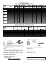
A. Unit shall be rated in accordance with ARI Standards
210/240-94 and 270-95 (Sound ratings for 270-95 are
not listed with ARI).
B. Unit shall be designed in accordance with UL Standard
1995.
C. Unit shall be manufactured in a facility registered to
ISO 9001 manufacturing quality standard.
D. Unit shall be UL listed and certified under Canadian
Standards as a total package for safety requirements.
E. Roof curb shall be designed to conform to NRCA
Standards.
F. Insulation and adhesives shall meet NFPA 90A
requirements for flame spread and smoke generation.
G. Cabinet insulation shall meet ASHRAE Standard 62P.
1.03 DELIVERY, STORAGE AND HANDLING
Unit shall be stored and handled per manufacturer’s
recommendations.
PART 2 — PRODUCTS
2.01 EQUIPMENT
A. General:
Factory-assembled, single-piece, heating and cooling unit.
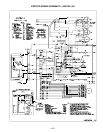
Contained within the enclosure shall be all factory wiring,
piping, controls, refrigerant charge with R-410A refrigerant,
and special features required prior to field start-up.
B. Unit Cabinet:
1. Unit Cabinet shall be constructed of phosphated,
zinc-coated, pre-painted steel capable of with-
standing 500 hours in salt spray.
2. Normal service shall be through a single removable
cabinet panel.
3. The unit shall be constructed on a rust proof
basepan that has an externally trapped, integrated
sloped drain pan.
4. Evaporator fan compartment top surface shall be
insulated with a minimum 1/2-in. thick, flexible
fiberglass insulation, coated on the air side and
retained by adhesive and mechanical means. The
evaporator wall sections will be insulated with a
minimum semi-rigid foil-faced board capable of
being wiped clean. Aluminum foil-faced fiberglass
insulation shall be used in the entire indoor air
cavity section.
5. Unit shall have a field-supplied condensate trap.
C. Fans:
1. The evaporator fan shall be 3-speed, direct-drive,
as shown on equipment drawings or factory
optional variable speed motor and control.
2. Fan wheel shall be made from steel, and shall be
double-inlet type with forward curved blades with
corrosion resistant finish. Fan wheel shall be
dynamically balanced.
3. Condenser fan shall be direct drive propeller type
with aluminum blades riveted to corrosion resistant
steel spiders, be dynamically balanced, and
discharge air vertically.
D. Compressor:
1. Fully hermetic compressors with factory-installed
vibration isolation.
2. Scroll compressors shall be standard on all units.
E. Coils:
Evaporator and condenser coils shall have aluminum
plate fins mechanically bonded to seamless copper
tubes with all joints brazed. (Copper/copper and vinyl-
coated construction available as option). Tube sheet
openings shall be belled to prevent tube wear.
F. Heating Section:
1. Induced-draft combustion type with energy saving
direct spark ignition system and redundant main
gas valve.
2. Induced-draft motors shall be provided with solid-
state hall-effect sensor to ensure adequate airflow
for combustion.
3. The heat exchangers shall be constructed of
aluminized steel for corrosion resistance.
4. Burners shall be of the in-shot type constructed of
aluminum coated steel.
5. All gas piping and electric power shall enter the unit
cabinet at a single location.
G. Refrigerant Components:
Refrigerant expansion shall be of the fixed orifice type.
H. Filters:
Filter section shall consist of field-installed, throwaway,
1-in. thick fiberglass filters of commercially available
sizes.
I. Controls and Safeties:
1. Unit controls shall be complete with a self-
contained low voltage control circuit.
2. Compressors shall incorporate a solid-state
compressor protector that provides reset
capability.
3. Unit shall provide high and loss-of-charge/low
pressure safety protection.
J. Operating Characteristics:
1. Unit shall be capable of starting and running at
125°F ambient outdoor temperature exceeding
maximum load criteria of ARI Standard 210.
2. Compressor with standard controls shall be capa-
ble of operation down to 40 F ambient outdoor tem-
perature. (55°F with ICM FIOP)
3. Units shall be provided with fan time delay to pre-
vent cold air delivery before the heat exchanger
warms up.
4. Unit shall be provided with 30-second fan time de-
lay after the thermostat is satisfied with standard in-
door blower.
5. On ICM FIOP fan off delay for cooling is selected
on Easy Select™ Board.
GUIDE SPECIFICATIONS