—14—
Y2
TB2
HEAT PUMP A
541A180
R
B
W1
A2
Y1
Q
C
P
X
1
2
TB2
HEAT PUMP B
575C120
G2/(W)
G3/(Y)
COM
G
MED(HEAT)
HI(COOL)
(VALVE)
FAN
LO
G2/(W)
G3/(Y)
COM
G
MED(HEAT)
HI(COOL)
(VALVE)
FAN
LO
R
Y1
Y2
W1
W2
G
C
X
WHT
WHT
C2
IFC
C1
R
Y1
Y2
W1
W2
G
C
X
524A-H
HEAT ACCESSORY
W1
W2
C
524A-H300
TERMINAL BLOCK
TB1
FIELD POWER
WIRING
DISCONNECT
FIELD
POWER
SUPPLY
3-Ph ONLY
L1
L2
L3
EQUIP GND
TB1
HC1
HC1
CIRCUIT BREAKER
(5 HP AND LARGER)
UNIT WIRING
IFM
BLK
BLK
BLK
21
22
23
12
13
11
1
2
3
HTR1
IFC
RELAY BOARD
(33ZCRLYBRD)
RELAY BOARD
(33ZCRLYBRD)
TSTAT*
CR
CR
R
Y1
Y2
W1
W2
G
C
X
CR
LEGEND
*Do not configure TSTAT for heat pump.
NOTE: Use copper conductors only.
CR — Control Relay (Field-Supplied)
EQUIP — Equipment
GND — Ground
HC — Heating Contactor
HTR — Electric Heater
IFC — Indoor-Fan Contactor
IFM — Indoor-Fan Motor
TB — Terminal Block
TSTAT — Thermostat
Factory Wiring
Field Control Wiring
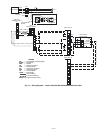
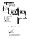
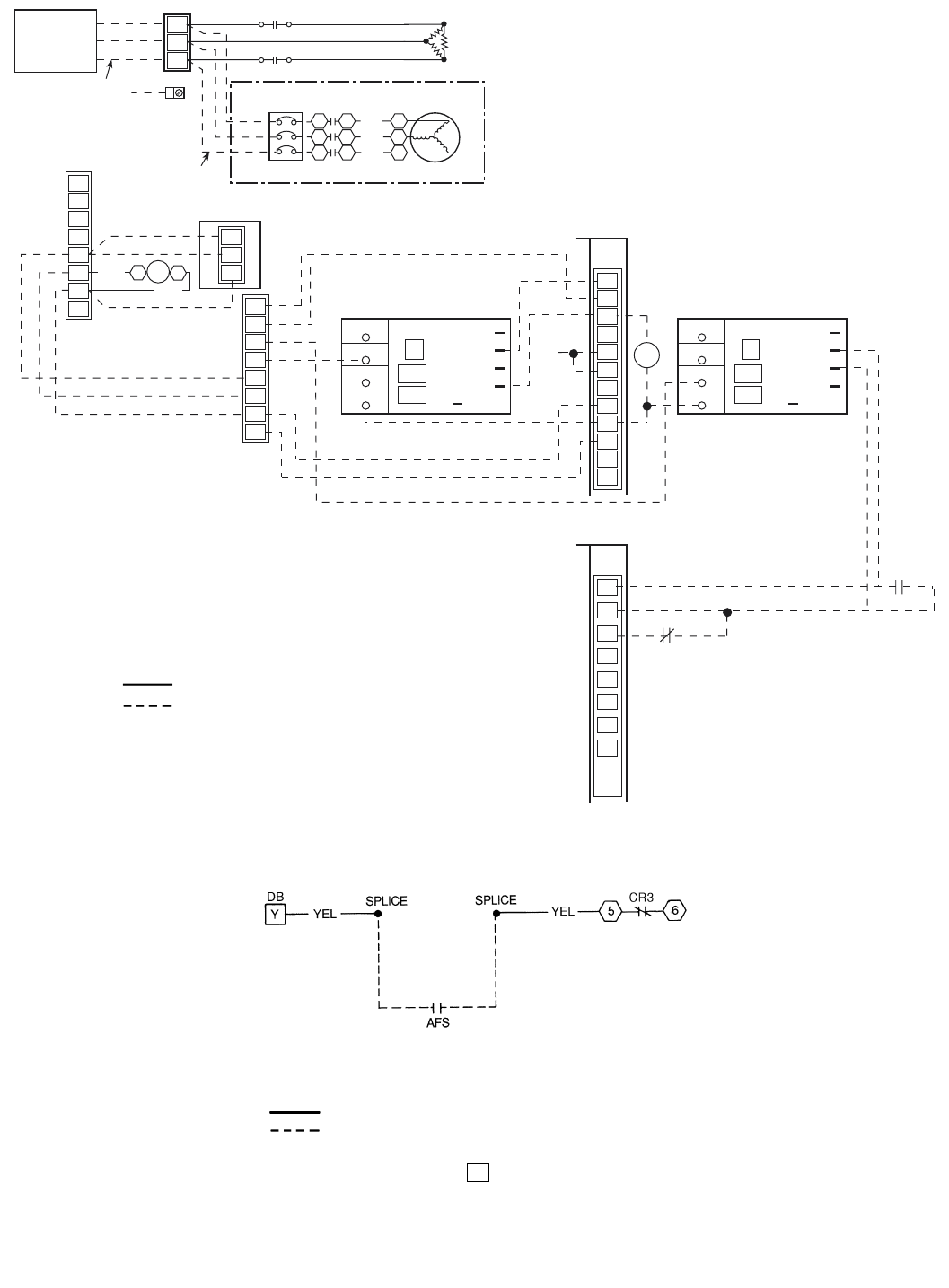
Fig. 13 — Wiring Diagram — Duplex 575C120 and 541A180 With 524A-H300 and Electric Heat
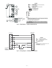
LEGEND
NOTES:
1. Locate YEL wire between on DB and terminal 5 of CR3
and cut.
2. Splice airflow switch (AFS) (field supplied) contact wires (field
provided) to two ends of cut YEL wire as depicted.
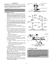
Fig. 14 — Typical Field Wiring for Airflow Switch —
541A180/524A-H
AFS — Airflow Switch (Sail Switch)
CR — Control Relay
DB — Defrost Board
Factory Wiring
Field Control Wiring
Y


