


116
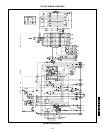
TYPICAL WIRING SCHEMATIC (cont)
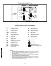
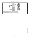
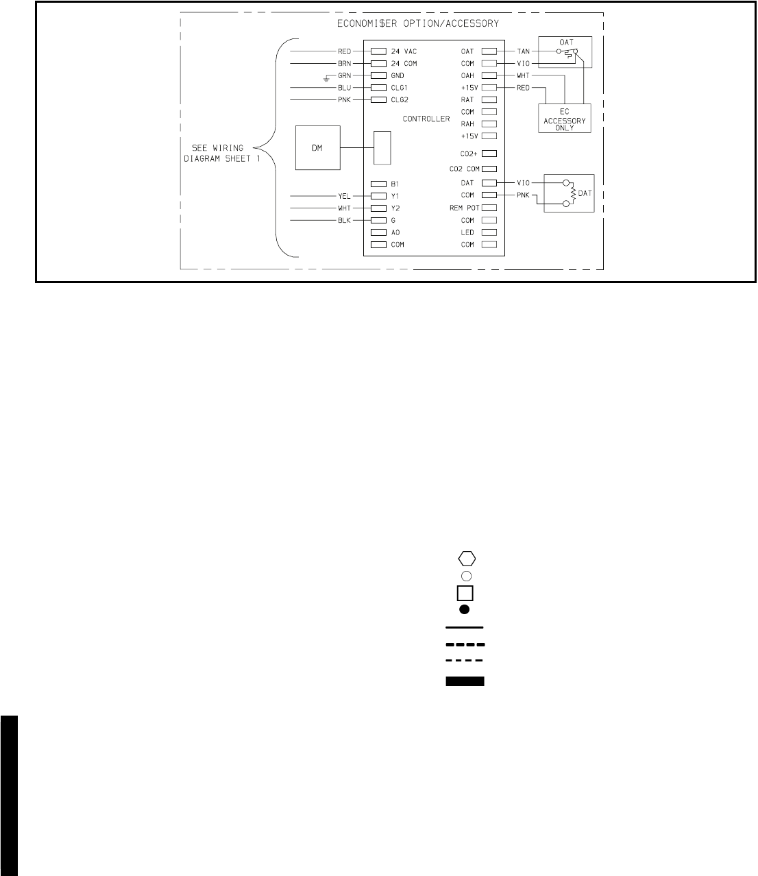
LEGEND AND NOTES FOR TYPICAL WIRING SCHEMATIC
AHA —
Adjustable Heat Anticipator
BKR W/AT —
Breaks with Amp Turns
C —
Contactor, Compressor
CAP —
Capacitor
CB —
Circuit Breaker
CC —
Cooling Compensator
CH —
Crankcase Heater
CLO —
Compressor Lockout
COMP —
Compressor Motor
CT —
Current Transformer
CTD —
Compressor Time Delay
DAT —
Discharge Air Thermistor
DB —
Defrost Board
DFT —
Defrost Thermostat
DM —
Damper Motor
DR —
Defrost Relay
DU —
Dummy Terminal
EC —
Enthalpy Control
EQUIP —
Equipment
FL —
Fuse Link
FPT —
Freeze Protection Thermostat
GND —
Ground
HC —
Heater Contactor
HPS —
High-Pressure Switch
HR —
Heat Relay
HTR —
Heater
IFC —
Indoor-Fan Contactor
IFCB —
Indoor-Fan Circuit Breaker
IFM —
Indoor Fan Motor
IP —
Internal Protector
L —
Light
LOR —
Lock Out Relay
LPS —
Low-Pressure Switch
LS —
Limit Switch
OAT —
Outdoor-Air Thermostat
OFC —
Outdoor-Fan Contactor
OFM —
Outdoor Fan Motor
OP —
Overcurrent Protector
PL —
Plug Assembly
QT —
Quadruple Terminal
RVR —
Reversing Valve Relay
RVS —
Reversing Valve Solenoid
TB —
Terminal Block
TC —
Thermostat Cooling
TH —
Thermostat Heating
TRAN —
Transformer
Terminal (Marked)
Terminal (Unmarked)
Terminal Block
Splice
Factory Wiring
Field Wiring
Option/Accessory Wiring
To Indicate Common Potential Only:
Not To Represent Wiring
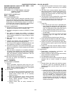
NOTES:
1. Compressor and/or fan motor(s) thermally protected. Three-phase motors are protected
against primary single phasing conditions.
2. If any of the original wire furnished must be replaced, it must be replaced with type 90° C
wire or its equivalent.
3. CB1,2 must trip amps are equal to or less than 156% FLA, IFCB 140%.
4. The CLO locks out the compressor to prevent short cycling on compressor overload and
safety devices. Before replacing CLO, check these devices.
5. Jumpers are omitted when unit is equipped with economizer.
6. Number(s) indicates the line location of used contacts. A bracket over (2) numbers signifies
a single-pole, double-throw contact. An underlined number signifies a normally-closed
contact. Plain (no line) number signifies a normally-open contact.
7. Remove jumper between terminals RC and RH.
50TFQ004-012
542J150,180