


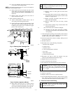
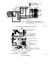
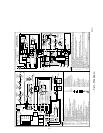
The electrical ground and polarity for 115-v wiring must be
maintained properly. Refer to Fig. 10 for field wiring information
and to Fig. 12 for unit wiring information.
NOTE: If the polarity is not correct, the STATUS LED on the
control center will flash rapidly and prevent the furnace from
operating. The control system also requires an earth ground for
proper operation of the control board and flame sensing.
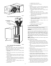
The 24-v circuit contains an automotive-type, 3-amp fuse located
on the control board. (See Fig. 11.) Any direct shorts of the 24-v
wiring during installation, service, or maintenance will cause this
fuse to blow. If fuse replacement is required, use ONLY a fuse of
identical size.
With power to the unit disconnected, check all electrical connec-
tions for tightness. Tighten all screws on electrical connections. If
any smoky or burned connections are found, disassemble the
connection, clean all parts, strip wire, and reassemble properly and
securely.
Reconnect electrical power to the unit and observe unit through 1
complete operating cycle. Electrical controls are difficult to check
without proper instrumentation; if there are any discrepancies in
the operating cycle, contact your dealer and request service.
For an explanation of fault codes, refer to service label located on
blower access door or Fig. 13, and the troubleshooting guide.
The control center stores 1 fault code (the last fault to occur) for a
period of 48 hrs or until the 115- or 24-v power is interrupted.
NOTE: Removing blower access door will open blower access
door switch and terminate 115-v power to control center, and fault
code will be erased. Look into blower access door sight glass for
current LED status.
1. To retrieve fault code, proceed with the following:
NOTE: NO thermostat signal may be present at control center,
and all blower time delay off periods must be completed.
a. Leave 115-v power to furnace turned on.
b. Look into blower access door sight glass for current
LED status.
NOTE: Leave blower access panel installed to maintain power to
control center to view current LED status.
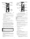
c. Remove control access door.
d. BRIEFLY remove either wire from the main limit switch
until LED goes out, then reconnect it.
NOTE: If wire to main limit is disconnected longer than 4 sec,
main blower starts, and retrieval request is ignored.
2. When above items have been completed, the following will
occur:
a. LED flashes a fault code 4 times. Record this fault code
for further troubleshooting.
b. Inducer motor starts and continues to run the entire
component test.
c. Hot surface ignitor is energized for 15 sec, then de-
energized.
d. Main blower operates at cooling speed for 10 sec, then
turns off.
e. Main blower operates at heating speed for 10 sec, then
turns off.
f. Inducer motor stops.
Items a through e above will assist in furnace troubleshoot-
ing since all components are functionally operated except
the gas valve. This procedure is also referred to as "Com-
ponent Test."
3. Operate furnace through 1 heat cycle to test for proper
operation and check LED status.
4. If furnace is operating properly and LED indicates proper
operation, replace control access door.
5. Component Test can also be initiated by performing the
following:
a. Remove control access door.
b. Remove blower access door.
c. Manually close blower access door switch.
WARNING: Blower access door switch opens 115-v
power to control center. No component operation can
occur. Caution must be taken when manually closing this
switch for service purposes. Failure to follow this warn-
ing could result in personal injury or death.
d. BRIEFLY short (jumper) TEST, 1/4-in. quick-connect
terminal on control center (adjacent to LED diagnostic
light), and Com terminal on thermostat connection
block. (See Fig. 11.)
NOTE: If TEST to Com terminals are jumpered longer than 2 sec,
LED will flash rapidly, and retrieval request will be ignored.
e. Component Test will function as described in item 2
above.
f. Check LED status.
g. If LED status indicates proper operation, release blower
access door switch, replace blower access door, and
replace control access door.
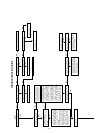
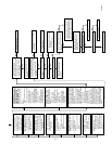
E. Troubleshooting
Refer to the service label. (See Fig. 13.) Pages 10 and 11 contain
a troubleshooting guide. This guide can be a useful tool in isolating
furnace operation problems. Beginning with the word "Start,"
answer each question and follow the appropriate arrow to the next
item.
The guide will help to identify the problem or failed component.
After replacing any component, verify correct operation sequence.
—6—