


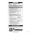
11 NO PREVIOUS FAULT - Faults
are erased after 48 hrs or
whenever power (115V or 24V)
is interrupted. Run system
through a heating or cooling
cycle to recheck system.
12 BLOWER ON AFTER POWER
UP (115V OR 24V) - Normal
operation. Blower will run for 90
sec when furnace power is
interrupted during a call for heat
and R-W closes.
13 LIMIT OR FLAME ROLLOUT
SWITCH LOCKOUT - Limit
switch was open longer than
3 minutes. Auto-reset will occur
after 3 hrs. Flame rollout switch
requires manual reset.
See No. 33
14 IGNITION LOCKOUT - System
failed to ignite gas and prove
flame in 4 attempts. Control will
auto-reset in 3 hrs.
See No. 34
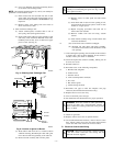
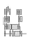
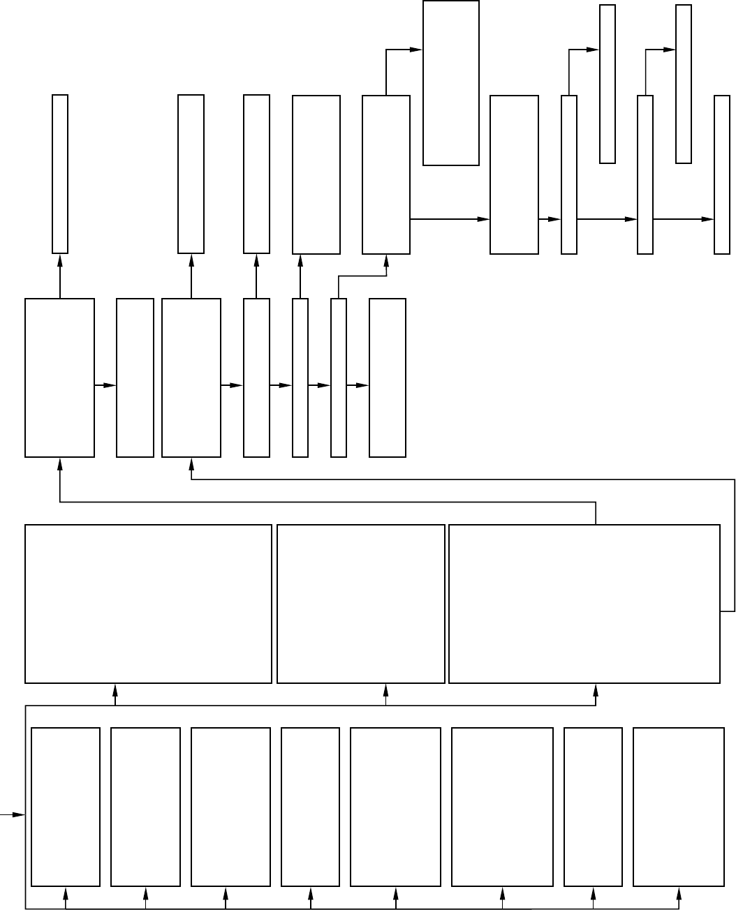
21 GAS HEATING LOCKOUT -
Turn off power and wait 5
minutes to retry.
Check for:
Unplug ignitor harness from control
center and inititate another
component test sequence and check
for 115v between pins 1 and 2 on
the board. Was there 115v present
for the 17 sec period?
Replace control board.
Check for continuity in the harness
and ignitor. Replace defective
component.
Reconnect the R thermostat lead
and set thermostat to call for heat.
Connect voltmeter across gas valve
connections. Does gas valve
receive 24v?
Check connections. If OK, replace
control board.
Does gas valve open and allow gas
to flow?
Check that all gas valves are turned
on. Replace valve.
Do main burners ignite?
Do main burners stay on?
Allow blower to come on and repeat
test to check for intermittent
operation.
Repeat call for heat and check flame
sensor current during trial for ignition
period. Is the dc microamperes
below 0.5?
Check connections including equipment
ground and retry. Green wire must be
connected to furnace sheet metal. If
current is near typical value and control
will not stay on, replace control board.
Clean flame sensor with fine
sandpaper and recheck current.
Current is nominally 4.0 to 6.0
microamps DC.
Is current near typical value?
Replace electrode.
Will main burner ignite and stay on?
Replace control board.
Fixed.
• Stuck closed gas valve relay
on control.
• Miswire or short to gas valve
wire.
22 ABNORMAL FLAME PROVING
SIGNAL - Flame was sensed
while gas valve was
de-energized. Inducer will run
until fault is cleared.
Check for:
• Stuck open gas valve solenoid
or leak.
• Defective control board.
23 PRESSURE SWITCH WILL
NOT OPEN - Check for:
• Disconnected or obstructed
pressure tubing.
• Defective pressure switch.
24 LOW-VOLTAGE FUSE IS
OPEN - Check for:
• Short in low-voltage wiring
including thermostat leads
shorting to ductwork or
furnace cabinet. Disconnect
thermostat leads to isolate
short circuit.
31 PRESSURE, DRAFT
SAFEGUARD (WHEN USED),
OR AUXILIARY LIMIT (WHEN
USED) SWITCH WILL NOT
CLOSE OR REOPEN - If open
longer than 5 minutes, inducer
shuts off for 15 minutes before
retry.
Check for:
• Proper vent sizing or pitch or
sag.
• Vent restrictions or high winds.
• Defective inducer motor.
• Low-line voltage (115v).
• Motor start capacitor.
• Low inlet gas pressure.
• Defective pressure switch or
connections. If it opens after
trial for igniton period, blower
will come on for 90 sec
recycle delay.
Inadequate combustion air
(for draft safeguard and
auxiliary limit switches only).
33 LIMIT OR FLAME ROLLOUT
SWITCH IS OPEN - If limit
switch is open longer than 3
minutes, code changes to No. 13.
Check for:
• Blower motor failure.
• Motor start capacitor.
• Open flame rollout switch,
manual reset.
•
Dirty or restrictive filter.
Defective limit switch or
connections.
Loose blower wheel.
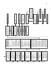
34 IGNITION PROVING FAILURE -
If flame is not sensed during the
trial for ignition period, the control
will repeat the ignition sequence
3 more times before going into
lockout, No. 14.
If flame signal is lost after trial for
ignition period, blower will come
on for 90 sec recycle delay.
Check for the following items first
before proceding to the next step.
• Gas valve turned off.
• Manual shut-off valve.
• Green wire must be connected
to furnace sheet metal.
To determine whether the
problem is in the gas valve,
igniter, or flame sensor, the
system can be operated in the
component test mode to check
out the ignitor. First, remove the
R thermostat connection from the
control board and initiate the
component test sequence. Does
the ignitor glow orange/white hot
by the end of the 17 sec warm-up
period?
Check for:
• Inadequate flame carryover on
rough ignition.
• Low inlet gas pressure.
NO
YES
YES
YES
YES
YES
YES
YES
YES
YES
NO
NO
NO
NO
NO
NO
NO
NO
•
•
Inadequate combustion air
supply (flame rollout
switch only).
•
Restricted duct system.•
•
A98523
—11—