


(2.) Use 1/4-in. diameter wire brush (commonly known
as 25-caliber rifle cleaning brush).
NOTE: The materials needed in items (1.) and (2.) can usually be
purchased at local hardware stores.
(3.) Insert twisted wire end of brush into end of steel
spring cable, and crimp tight with crimping tool or
strike with ball-peen hammer. TIGHTNESS is very
important.
(4.) Remove metal screw fitting from wire brush to
allow insertion into cable.
b. Clean each heat exchanger cell.
(1.) Attach variable-speed, reversible drill to end of
steel spring cable (end opposite brush).
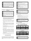
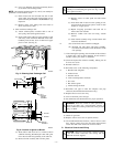
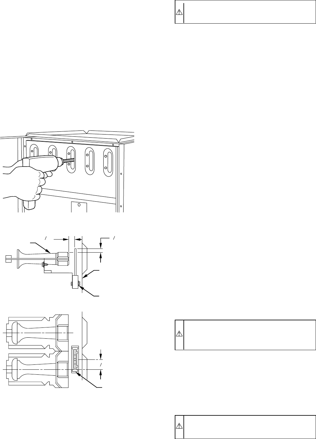
(2.) Insert brush end of cable into upper opening of cell
and slowly rotate with drill. DO NOT force cable.
Gradually insert at least 36 in. of cable into 2 upper
passes of cell. (See Fig. 8.)
(3.) Work cable in and out of cell 3 or 4 times to obtain
sufficient cleaning. DO NOT pull cable with great
force. Reverse drill and gradually work cable out.
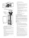
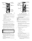
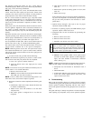
(4.) Remove burner assembly and cell inlet plates.
CAUTION: Be very careful when removing the burner
assembly to avoid breaking the ignitor. See Fig. 9 for the
correct ignitor location.
(5.) Replace screws in center panel and cells before
cleaning.
(6.) Insert brush end of cable in lower opening of cell,
and proceed to clean 2 lower passes of cell in same
manner as 2 upper passes.
(7.) Repeat foregoing procedures until each cell in
furnace has been cleaned.
(8.) Remove residue from each cell using vacuum
cleaner.
(9.) Clean burner assembly using vacuum cleaner with
soft brush attachment.
(10.) Clean flame sensor with fine sandpaper.
(11.) Reinstall cell inlet plates and burner assembly.
Care must be exercised to center the burners in the
cell openings.
9. After cleaning flue openings, check sealant on flue collector
to ensure that it has not been damaged. If new sealant is
needed, contact your dealer or distributor.
10. Clean and replace flue collector assembly, making sure all
8 screws are secure.
11. Reinstall relief box.
12. Reconnect wires to the following components.
a. Blocked vent safeguard
b. Inducer motor
c. Pressure switch
d. Limit overtemperature switch(es)
e. Gas valve
f. Hot surface ignitor
g. Flame-sensing electrode
13. Reconnect vent pipe to relief box. Replace vent pipe
enclosure (downflow/horizontal furnace only).
14. Replace blower access door only.
15. Turn on electrical power and gas.
16. Set thermostat and check furnace for proper operation.
WARNING: Never use a match or other open flame to
check for gas leaks. Use a soap-and-water solution. A
failure to follow this warning could result in fire, personal
injury, or death.
17. Check for gas leaks.
18. Replace control access door on upflow furnace.
19. On downflow/horizontal furnaces, remove blower access
door, replace control access door first, then replace blower
access door and secure with screw in front of door.
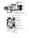
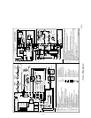
D. Electrical Controls and Wiring
CAUTION: There may be more than 1 electrical supply
to the unit. Check accessories and cooling unit for
additional electrical supplies.
Fig. 8—Cleaning Heat Exchanger Cell
A91252
Fig. 9—Position of Ignitor to Burner
A93347
BURNER
IGNITOR
11
32
"
7
8
"
C
L
C
L
IGNITOR
ASSEMBLY
CELL
PANEL
BURNER
13
32
"
HOT
SURFACE
IGNITOR
ASSEMBLY
—5—
→
→