


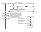

CAUTION: The ground wire from the gas valve MUST
be attached to the burner box attachment screw. Failure to
attach this ground wire to an adequate casing ground will
cause the furnace control to lock out.
NOTE: Be sure burner box gasket is installed between burner box
and cell panel. If gasket is damaged, replace it.
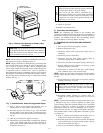
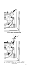
NOTE: Inspect combustion-air intake housing. If foamed gasket
was removed, check for any damage. If gasket is damaged in any
way, it must be repaired. To repair, remove damaged gasket
section, apply sealant releasing agent such as PAM cooking spray
or equivalent (must not contain corn or canola oil, aromatic or
halogenated hydrocarbons or inadequate seal may occur) to burner
box and apply a small bead of G.E. RTV 162, G.E. RTV 6702, or
Dow-Corning RTV 738 sealant to edge of combustion-air intake
housing. (See Fig. 7.)
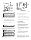
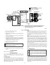
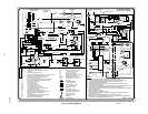
13. Refer to furnace wiring diagram and reconnect wires to
rollout switch, gas valve, igniter, and flame sensor.
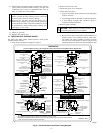
14. Reconnect pressure switch tubes to gas valve and intake
housing. Refer to tube routing label on main furnace door
for proper tube location. Be sure tubes are not kinked. (See
Fig. 8.)
15. Turn on gas and electrical supplies to furnace.
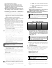
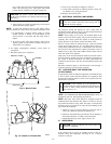
16. Check furnace operation through 2 complete heat operating
cycles. Look through sight glass in burner enclosure to
check burners. Burner flames should be clear blue, almost
transparent. (See Fig. 9.)
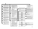
WARNING: FIRE OR EXPLOSION HAZARD
Failure to follow the safety warnings exactly could result
in serious injury, death, or property damage.
Never test for gas leaks with an open flame. Use a
commercially available soap solution made specifically
for the detection of leaks to check all connections. A fire
or explosion may result causing property damage, per-
sonal injury, or loss of life.
17. Check for gas leaks.
18. Replace main furnace door.
B. Secondary Heat Exchangers
NOTE: The condensing side (inside) of the secondary heat
exchangers CANNOT be serviced or inspected. A small number of
bottom outlet openings can be inspected by removing the inducer
assembly. See Flushing Collector Box and Drainage System
section for details on removing inducer assembly.
V. FLUSHING COLLECTOR BOX AND DRAINAGE
SYSTEM
1. Turn off gas and electrical supplies to furnace.
2. Remove main furnace door.
3. Disconnect inducer motor and pressure switch wires or
connectors.
4. Disconnect pressure switch tubes.
5. Disconnect vent pipe from inducer housing outlet by
loosening coupling clamp on inducer outlet.
6. Disconnect drain tube from inducer housing. (See Fig. 8.)
7. Remove inducer housing assembly by removing 4 bolts
attaching assembly to cell panel.
8. Flush inside of collector box with water until discharge
from condensate trap is clean and runs freely.
NOTE: Ensure the drain tube disconnected from the inducer
housing is higher than the collector box opening or water will flow
out tube.
9. Inspect inside area of collector box for any pieces of foreign
materials and remove if present.
CAUTION: DO NOT use wire brush or other sharp
object to inspect or dislodge materials in secondary heat
exchangers as failure of the secondary heat exchanger
will occur. Flush with water only.
10. Reassemble inducer assembly by reversing items 5-7.
Tighten the vent coupling clamp screw(s) to 15 in.-lb of
torque.
NOTE: If seal between the inducer housing and the collector box
is damaged in any way, it must be repaired. To repair, apply
sealant releasing agent such as PAM cooking spray or equivalent
(must not contain corn or canola oil, aromatic or halogenated
hydrocarbons which can cause an inadequate seal to occur) to
inducer housing. (See Fig. 10.) Apply a small bead of G.E. RTV
162, G.E. RTV 6702, or Dow-Corning RTV 738 sealant to groove
in collector box.
11. Refer to furnace wiring diagram and reconnect wires to
inducer motor and pressure switches or connectors.
12. Reconnect pressure tubes to pressure switches. See diagram
on main furnace door for proper location of tubes. Be sure
tubes are not kinked. (See Fig. 8.)
13. Turn on gas and electrical supplies to furnace.
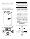
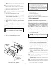
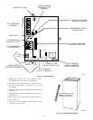
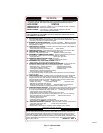
Fig. 6—Cleaning Inlet Openings of Primary Heat
Exchangers
A96305
PRIMARY HX
INLET OPENINGS
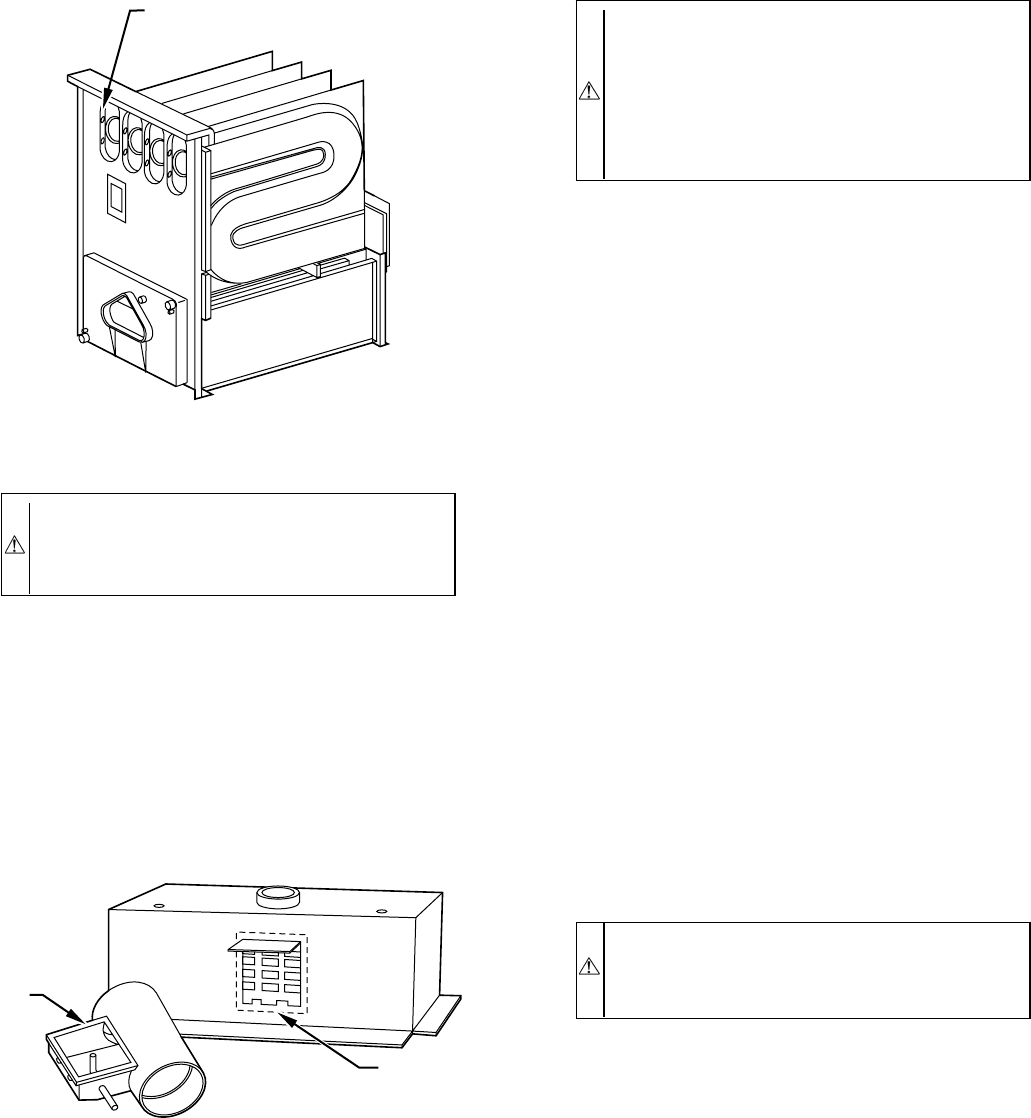
Fig. 7—Combustion-Air Intake Housing Gasket Repair
A93087
PAM
RTV
—6—