


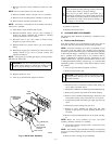
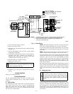
Fig. 17—Service Label
A02154
SERVICE
To initiate the component test sequence, shut OFF the room thermostat or disconnect
the "R" thermostat lead. Briefly short the TEST/TWIN terminal to the "Com 24V" ter-
minal. Status LED will flash code and then turn ON the inducer motor. The inducer
motor will run for the entire component test. The hot surface ignitor, blower motor
FAN speed (AMBER LED boards only) blower motor HEAT speed, and blower motor
COOL speed will be turned ON for 10-15 seconds each. Gas Valve and Humidifier
will not be turned on.
CONTINUOUS OFF - Check for 115VAC at L1 & L2, & 24VAC at SEC-1 & SEC-2.
CONTINUOUS ON - Control has 24VAC power.
RAPID FLASHING - Line voltage (115VAC) polarity reversed. If twinned,
refer to twinning kit instructions.
LED CODE
EACH OF THE FOLLOWING STATUS CODES IS A TWO DIGIT NUMBER WITH THE FIRST
DIGIT DETERMINED BY THE NUMBER OF SHORT FLASHES AND THE SECOND DIGIT BY
THE NUMBER OF LONG FLASHES.
STATUS
11 NO PREVIOUS CODE - Stored status code is erased automatically after 72
hours. On RED LED boards stored status codes can also be erased when power
(115 VAC or 24 VAC) to control is interrupted.
12 BLOWER ON AFTER POWER UP (115 VAC or 24 VAC) -Blower runs for 90
seconds, if unit is powered up during a call for heat (R-W closed) or R-W opens
during blower on-delay.
13 LIMIT CIRCUIT LOCKOUT - Lockout occurs if the limit or flame rollout switch is
open longer than 3 minutes.
- Control will auto reset after three hours. - Refer to #33.
14 IGNITION LOCKOUT - Control will auto-reset after three hours. Refer to #34.
21 GAS HEATING LOCKOUT - Control will NOT auto reset.
Check for: - Mis-wired gas valve -Defective control (valve relay)
22 ABNORMAL FLAME-PROVING SIGNAL - Flame is proved while gas valve is
de-energized. Inducer will run until fault is cleared. Check for:
- Leaky gas valve - Stuck-open gas valve
23 PRESSURE SWITCH DID NOT OPEN Check for:
- Obstructed pressure tubing. - Pressure switch stuck closed.
24 SECONDARY VOLTAGE FUSE IS OPEN Check for:
- Short circuit in secondary voltage (24VAC) wiring.
31 PRESSURE SWITCH DID NOT CLOSE OR REOPENED - If open longer than
five minutes, inducer shuts off for 15 minutes before retry. Check for:
- Excessive wind - Proper vent sizing - Defective inducer motor
- Low inducer voltage (115VAC) - Defective pressure switch
- Inadequate combustion air supply - Restricted vent
- Disconnected or obstructed pressure tubing
- Low inlet gas pressure (if LGPS used)
If it opens during blower on-delay period, blower will come on for the selected
blower off-delay.
33 LIMIT CIRCUIT FAULT - Indicates a limit, or flame rollout is open. Blower will
run for 4 minutes or until open switch remakes whichever is longer. If open
longer than 3 minutes, code changes to lockout #13. If open less than 3 minutes
status code #33 continues to flash until blower shuts off. Flame rollout switch
requires manual reset. Check for: - Restricted vent
- Proper vent sizing - Loose blower wheel - Excessive wind
- Dirty filter or restricted duct system.
- Defective blower motor or capacitor. - Defective switch or connections.
- Inadequate combustion air supply (Flame Roll-out Switch open).
34 IGNITION PROVING FAILURE - Control will try three more times before lockout
#14 occurs. If flame signal lost during blower on-delay period, blower will come
on for the selected blower off-delay. Check for: - Control ground continuity
- Flame sensor must not be grounded
- Oxide buildup on flame sensor (clean with fine steel wool).
- Proper flame sense microamps (.5 microamps D.C. min., 4.0 - 6.0 nominal).
- Gas valve defective or gas valve turned off - Manual valve shut-off
- Defective Hot Surface Ignitor
- Low inlet gas pressure
- Inadequate flame carryover or rough ignition
- Green/Yellow wire MUST be connected to furnace sheet metal
45 CONTROL CIRCUITRY LOCKOUT Auto-reset after one hour lockout due to;
- Gas valve relay stuck open - Flame sense circuit failure
- Software check error
Reset power to clear lockout. Replace control if status code repeats.
If status code recall is needed, briefly remove then reconnect one main limit wire to display
stored status code. On RED LED boards do not remove power or blower door before initiat-
ing status code recall. After status code recall is completed component test will occur.
COMPONENT TEST
327884-101 REV. A
—13—