


1. Turn off electrical supply to furnace.
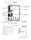
2. Remove main furnace door and blower access panel.
3. Disconnect blower motor wires from furnace control.
Field thermostat connections may need to be disconnected
depending on their length and routing.
4. Remove control box mounting screws, and position control
box, transformer, and door switch assembly to right side of
furnace casing.
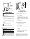
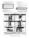
5. If condensate trap is located in left- or right-hand side of
furnace casing, proceed to item 6, otherwise remove trap
and tubing as described below (see Fig. 8, top left):
a. Disconnect field drain connection from condensate trap.
b. Disconnect drain and relief port tubes from condensate
trap.
c. Remove condensate trap from blower shelf.
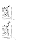
6. Remove screws securing blower assembly to blower shelf
and slide blower assembly out of furnace.
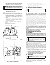
7. Clean blower wheel and motor by using a vacuum with soft
brush attachment. Be careful not to disturb balance weights
(clips) on blower wheel vanes. Do not bend wheel or blades
as balance will be affected.
8. If greasy residue is present on blower wheel, remove wheel
from the blower housing and wash it with an appropriate
degreaser. To remove wheel:
a. Mark blower wheel location on shaft before disassembly
to ensure proper reassembly.
b. Loosen setscrew holding blower wheel on motor shaft.
NOTE: Mark blower mounting arms and blower housing so each
arm is positioned at the same hole location during reassembly.
c. Mark blower wheel orientation and cutoff plate location
to ensure proper reassembly.
d. Remove screws securing cutoff plate and remove cutoff
plate from housing.
e. Remove bolts holding motor mounts to blower housing
and slide motor and mounts out of housing. Disconnect
capacitor and ground wire attached to blower housing
before removing motor. Motor mounts need not be
removed from motor.
f. Remove blower wheel from housing.
CAUTION: The blower wheel should not be dropped or
betn as balance will be affected.
g. Clean wheel per instructions on degreaser cleaner. Do
not get degreaser in motor.
9. Reassemble motor and blower wheel by reversing items 8b
through 8f. Ensure wheel is positioned for proper rotation.
Be sure to attach ground wire. Tighten set-screw to 140 to
160 in.-lb torque.
10. Reinstall blower assembly in furnace.
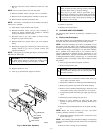
11. Reinstall control box, transformer, and door switch assem-
bly on blower shelf.
12. Reinstall condensate trap and tubing if previously removed.
a. Reinstall condensate trap in hole in blower shelf.
b. Connect condensate trap drain tubes. See Fig. 8 or tubing
diagram on main furnace door for proper tube location.
NOTE: Ensure tubes are not kinked or pinched, as this will affect
operation.
(1.) Connect 1 tube (blue or blue and white striped)
from collector box.
(2.) Connect 1 tube (violet or unmarked) from inducer
housing.
(3.) Connect 1 tube (relief port, green or pink) from
collector box.
c. Connect field drain to condensate trap.
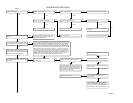
13. Reconnect wires.
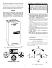
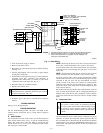
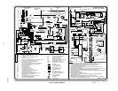
Refer to furnace wiring diagram and connect thermostat
leads if previously disconnected. (See Fig. 15.)
NOTE: Refer to Table 1 for motor speed lead reconnection if
leads were not identified before disconnection.
CAUTION: Heating speed selection MUST be adjusted
to provide proper temperature rise as specified on the
rating table. Failure to adjust the heating speed may
shorten heat exchanger life.
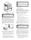
14. Turn on electrical supply. Manually close blower access
door switch. Use a piece of tape to hold switch closed.
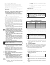
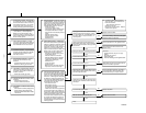
Check for proper rotation and speed changes by perroming
a componenet self-test as shown at the bottom of Service
Label. (See Fig. 17.)
WARNING: Blower access door switch opens 115-v
power to furnace control. No component operation can
occur. Caution must be taken when manually closing this
switch for service purposes. Failure to follow this warn-
ing could result in personal injury or death.
15. If furnace is operating properly, release blower access door
switch, replace blower access door, and replace main
furnace door.
III. CLEANING BURNERS
The following items should be performed by a qualified service
technician. If the burners develop an accumulation of light dirt or
dust, they may be cleaned by using the following procedure:
1. Turn off gas and electrical supplies to furnace.
2. Remove main furnace door.
3. Remove burner box cover.
4. Using backup wrench, disconnect gas supply pipe from
furnace gas control valve.
CAUTION: Label all wires prior to disconnection when
servicing controls. Wiring errors can cause improper and
dangerous operation.
5. Remove wires from gas valve. Note location for reassem-
bly.
6. Remove burner box pressure tube from gas valve regulator
fitting.
TABLE 1—SPEED SELECTION
COLOR SPEED
FACTORY
ATTACHED TO
Black High Cool
Yellow (When Present) Medium High Spare
Blue Medium Low Heat
Red Low Spare
White Common Com
—4—