


11
Contactor Shorted Detection
If there is compressor voltage sensed when there is no demand for
compressor operation, the contactor may be stuck closed or there
may be a wiring error. The control will flash the appropriate fault
code.
If the control senses the compressor voltage after start--up and is
then absent for 10 consecutive seconds while cooling or heating
demand exists, the thermal protector is open. The control
de--energizes the compressor contactor for 15 minutes, but
continues to operate the outdoor fan. The control Status LED will
flash the appropriate code shown in Table 5. After 15 minutes,
with a call for low or high stage cooling or heating, the compressor
contactor is energized. If the thermal protector has not re--set, the
outdoor fan is turned off. If the call for cooling or heating
continues, the control will energize the compressor contactor every
15 minutes. If the thermal protector closes, (at the next 15 minute
interval check) the unit will resume operation.
If the thermal cutout trips for three consecutive cycles, then unit
operation is locked out for 4 hours and the appropriate fault code is
displayed.
No 230V at Compressor Contactor
If the compressor voltage is not sensed when the compressor
should be starting, the appropriate contactor may be stuck open or
there is a wiring error. The control will flash the appropriate fault
code. Check the contactor and control box wiring.
Troubleshooting units for proper switching between
low & high
stages
Check the suction pressures at the service valves. Suction pressure
should be reduced by 3--10% when switching from low to high
capacity.
Compressor current should increase 20--45% when switching from
low to high stage. The compressor solenoid when energized in
high stage, should measure 24vac.
When the compressor is operating in low stage the 24v DC
compressor solenoid coil is de--energized. When the compressor is
operating in high stage, the 24v DC solenoid coil is energized. The
solenoid plug harness that is connected to the compressor HAS an
internal rectifier that converts the 24v DC signal to 24v AC. DO
NOT INSTALL A PLUG WITHOUT AN INTERNAL
RECTIFIER.
Unloader Test Procedure
The unloader is the compressor internal mechanism, controlled by
the DC solenoid, that modulates between high and low stage. If it
is suspected that the unloader is not working, the following
methods may be used to verify operation.
1. Operate the system and measure compressor amperage.
Cycle the unloader on and off at 30 second plus intervals at
the User Interface (from low to high stage and back to low
stage). Wait 5 seconds after staging to high before taking a
reading. The compressor amperage should go up or down
at least 20 percent.
2. If the expected result is not achieved, remove the solenoid
plug from the compressor and with the unit running and the
User Interface or thermostat calling for high stage, test the
voltage output at the plug with a DC voltmeter. The read-
ing should be 24 volts DC.
3. If the correct DC voltage is at the control circuit molded
plug, measure the compressor unloader coil resistance. The
resistance should be 32 to 60 ohms depending on com-
pressor temperature. If the coil resistance is infinite, much
lower than 32 ohms, or is grounded, the compressor must
be replaced.
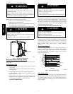
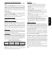
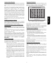
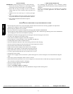
Temperature Thermistors
Thermistors are electronic devices which sense temperature. As the
temperature increases, the resistance decreases. Thermistors are
used to sense outdoor air (OAT) and coil temperature (OCT).
Refer to Fig. 7 for resistance values versus temperature.
0
10
20
30
40
50
60
70
80
90
0
(-17.77)
20
(-6.67)
40
(4.44)
60
(15.56)
80
(26.67)
100
(37.78)
120
(48.89)
TEMPERATURE °F (°C)
RESISTANCE (KOHMS)
THERMISTOR CURVE
A08054
Fig. 7 -- Resistance Values Versus Temperature
If the outdoor air or coil thermistor should fail, the control will
flash the appropriate fault code. (See Table 5.)
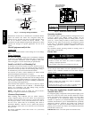
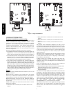
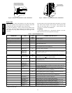
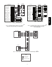
IMPORTANT: The outdoor air thermistor and coil thermistor
should be factory mounted in the final locations. Check to ensure
thermistors are mounted properly per Fig. 8 and Fig. 9.
Thermistor Sensor Comparison
The control continuously monitors and compares the outdoor air
temperature sensor and outdoor coil temperature sensor to ensure
proper operating conditions. The comparison is:
S In cooling if the outdoor air sensor indicates ≥ 10_F
(≥ 5.6_C) warmer than the coil sensor (or) the outdoor air sensor
indicates ≥ 20_F(≥ 11_C) cooler than the coil sensor, the
sensors are out of range.
S In heating if the outdoor air sensor indicates ≥ 35_F(≥ 19.4_C)
warmer than the coil sensor (or) the outdoor air sensor indicates
≥ 10_F(≥ 5.6_C) cooler than the coil sensor, the sensors are out
of range.
If the sensors are out of range, the control will flash the appropriate
fault code as shown in Table 5.
The thermistor comparison is not performed during low ambient
cooling or defrost operation.
Failed Thermistor Default Operation
Factory defaults have been provided in the event of failure of
outdoor air thermistor (OAT) and/or outdoor coil thermistor
(OCT).
If the OAT sensor should fail, low ambient cooling will not be
allowed and the one--minute outdoor fan off delay will not occur.
Defrost will be initiated based on coil temperature and time.
If the OCT sensor should fail, low ambient cooling will not be
allowed. Defrost will occur at each time interval during heating
operation, but will terminate after 5 minutes.
If there is a thermistor out of range error, defrost will occur at each
time interval during heating operation, but will terminate after 5
minutes.
Count the number of short and long flashes to determine the
appropriate flash code. Table 5 gives possible causes and actions
related to each error.
286B / 289B