


10
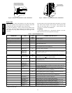
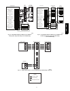
Field Connections
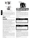
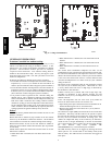
On non--communicating (non--Evolution) system, the two--stage
control receives 24vac low--voltage control system inputs through
the R, C, Y1, Y2 and O connections located at the bottom of the
control board (see Fig. 6.) On a non--communicating system,
output W1 is connected at the bottom of the control board for
auxiliary heat.
For a communicating system, use the ABCD Evolution
connections.
Two Stage Compressor
The two stage compressor contains motor windings that provide
2--pole (3500 RPM) operation.
Compressor Internal Relief
The compressor is protected by an internal pressure relief (IPR)
which relieves discharge gas into the compressor shell when
differential between suction and discharge pressure exceeds
550--625 psi. The compressor is also protected by an internal
overload attached to motor windings.
Compressor Control Contactor
The contactor has a 24volt coil. The electronic control board
controls the operation of the contactor.
TROUBLESHOOTING
Systems Communication Failure
If communication with the Evolution control is lost with the User
Interface, the control will flash the appropriate fault code. (See
Table 5.) Check the wiring to the User Interface and the indoor and
outdoor units.
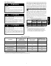
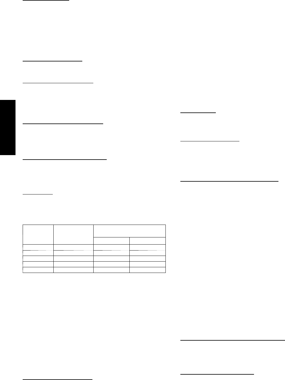
Model Plug
Each control board contains a model plug. The correct model plug
must be installed for or the system to operate properly. (See Table
4.)
Table 4 – Model Plug Information
MODEL
NUMBER
MODEL PLUG
NUMBER
PIN RESISTANCE
( K --- oh ms )
Pi ns 1 --- 4 Pi ns 2 --- 3
286BNA024 HK70EZ041 18 91
286BNA036 HK70EZ043 18 150
289BNA036 HK70EZ012 5.1 180
286BNA048 HK70EZ045 18 220
286BNA060 HK70EZ047 18 360
The model plug is used to identify the type and size of unit to the
control.
On new units, the model and serial numbers are input into the
board’s memory at the factory. If a model plug is lost or missing at
initial installation, the unit will operate according to the
information input at the factory and the appropriate error code will
flash temporarily. An RCD replacement board contains no model
and serial information. If the factory control board fails, the model
plug must be transferred from the original board to the replacement
board for the unit to operate.
NOTE: The model plug takes priority over factory model
information input at the factory. If the model plug is removed after
initial power up, the unit will operate according to the last valid
model plug installed, and flash the appropriate fault code
temporarily.
Pressure Switch Protection
The outdoor unit is equipped with high-- and low--pressure
switches. If the control senses the opening of a high-- or
low--pressure switch, it will respond as follows:
1. De--energize the compressor contactor.
2. Keep the outdoor fan operating for 15 minutes.
3. Display the appropriate fault code (see Table 5).
4. After a 15 minute delay, if there is a call for cooling or heat-
ing and LPS or HPS is reset, the compressor contactor is
energized.
5. If LPS or HPS has not closed after a 15 minute delay, the
outdoor fan is turned off. If the open switch closes anytime
after the 15 minute delay, then resume operation with a call
for cooling or heating.
6. If LPS or HPS trips 3 consecutive cycles, the unit operation
is locked out for 4 hours.
7. In the event of a high--pressure switch trip or high--pressure
lockout, check the refrigerant charge, outdoor fan operation,
and outdoor coil (in cooling) for airflow restrictions, or in-
door airflow in heating.
8. In the event of a low--pressure switch trip or low--pressure
lockout, check the refrigerant charge and indoor airflow
(cooling) and outdoor fan operation and outdoor coil in
heating.
Control Fault
If the outdoor unit control board has failed, the control will flash
the appropriate fault code (see Table 5). The control board should
be replaced.
Brown--Out Protection
If the line voltage is less than 187v for at least 4 seconds, the
appropriate compressor contactor and fan relay are de--energized.
Compressor and fan operation are not allowed until voltage is a
minimum of 190v. The control will flash the appropriate fault code
(see Table 5).
230V Brown--Out Protection Defeated
The brownout feature can be defeated if needed for severe noisy
power conditions. This defeat should always be a last resort to
solving the problem. Defeat is available on the User Interface
setup screen (available with SYSTXBBUID01--C), or can be
initiated through the forced defrost pins for non--communicating
systems as follows:
The brownout toggle is accomplished by sorting the defrost pins
from power up with the OAT and OCT sensor connector removed.
After 3 seconds, the status of the force defrost short and the
OAT/OCT as open will be checked. If correct, then the brownout
will be toggled.
Status code 6 shows the brownout is disabled.
Status code 5 shows the brownout is active.
After the brownout defeat is set, power down and reinstall the
OAT/OCT sensor and remove the short from the forced defrost
pins. As long as the short on the forced defrost remains, the OAT
and OCT faults will not be cleared. The code will continue to be
flashed.
The control is shipped with the brownout active. The change in
status is remembered until toggled to a new status. A power
down/power up sequence will not reset the status. it may be
necessary to do the toggle twice to cycle to the desired state of the
defeat.
230V Line (Power Disconnect) Detection
If there is no 230v at the compressor contactor(s) when the indoor
unit is powered and cooling or heating demand exists, the
appropriate fault code is displayed. Verify the disconnect is closed
and 230v wiring is connected to the unit.
Compressor Voltage Sensing
The control board input terminals labeled VS and L2 (see Fig. 6)
are used to detect compressor voltage status and alert the user of
potential problems. The control continuously monitors the high
voltage on the run capacitor of the compressor motor. Voltage
should be present any time the compressor contactor is energized
and voltage should not be present when the contactor is
de--energized.
286B / 289B