


1.5 GAS SUPPLY CONNECTION - FORCED DRAFT UNITS
The installation must conform completely to the
requirements of the authority having jurisdiction,
or in the absence of such, requirements shall
conform in the U.S. to the current National Fuel
Gas Code, ANSI Z223.1-1984, or in Canada to
the current Installation Code for Gas Burning
Appliances and Equipment (CAN/CGA B149.1-
M91), or Oil Burning Equipment (CSA B139-
M91), and applicable regional regulations for the
class; which should be followed carefully in all
cases.
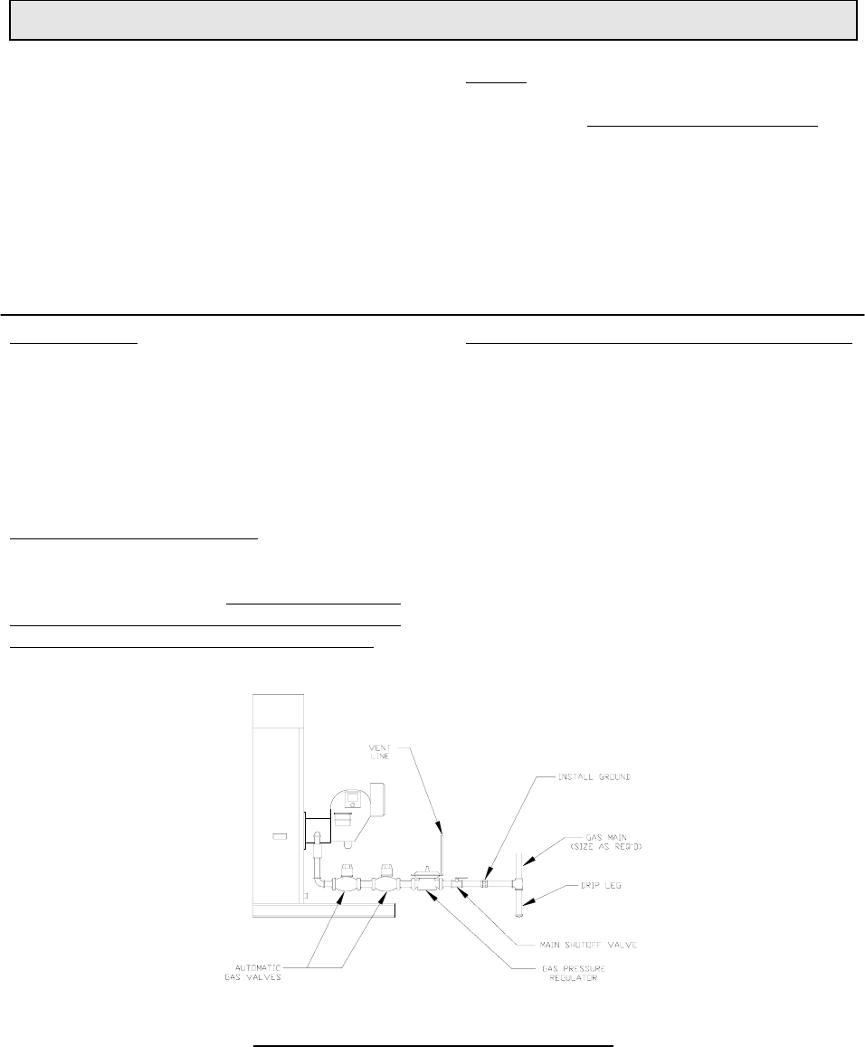
Drip leg
must be installed on gas supply piping.
Consult the local gas utility company
for
inspection and authorization of all gas supply
piping and flue connections.
The regulator vent line must be vented to outside
of building on any boiler equipment with electric
gas pilot ignition.
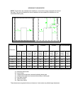
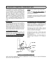
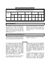
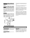
1.5.1 DRIP LEG
A drip leg or sediment trap must be installed in
the gas supply line. See Fig. 1.5A. The gas line
must be connected to a supply main at least as
large as the gas train connection at the boiler.
This connection should be made with a union so
that the boiler gas train components and burner
may be easily removed, if necessary, for service.
1.5.2 GAS PIPING LEAK TEST
After completion of the gas piping hookup, the
installation must be checked for leaks, using a
soap and water solution. Disconnect the boiler
and gas train from the gas supply piping during
any pressure testing of the gas supply system.
1.5.3 VENTING OF GAS TRAIN COMPONENTS
Gas pressure regulator - The regulator must be
vented to the outside air, using minimum 1/4"
tubing or pipe. The vent line should terminate in a
downward direction to be free of restriction.
Diaphragm gas valves (V48A or V88A) - The vent
line off of these gas valves must be vented to
outdoors, the same as the regulator.
Normally open vent valves - These valves must
be piped to outdoors using pipe no smaller than
that of the valve.
Gas pressure switches - Vent these switches to
outdoors using a minimum of 1/4" tubing or
piping.
FIGURE 1.5A: GAS BURNER CONNECTION
NOTE: USE PIPE COMPOUND, WHICH IS RESISTANT TO THE ACTION OF LIQUID PETROLEUM
GAS. DO NOT USE TEFLON TAPE.