


NOTE
THE LOW FIRE ADJUSTMENT SHOULD
RESULT IN A GAS PRESSURE ON THE
BURNER MANIFOLD EQUAL TO 1" WATER
COLUMN FOR NATURAL GAS AND 3" FOR
PROPANE GAS.
2.1.5 MINIMUM INPUT ADJUSTMENT -
COMBINATION GAS VALVES (VR850 OR
VR852)
The minimum input on these gas valves is NOT
adjustable. The maximum input must be properly
set as outlined in Lighting Instructions. See the
manufacturer's instructions on the VR850 or
VR852 included in the Boiler Manual for further
information.
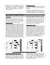
2.1.6 MINIMUM INPUT ADJUSTMENT - DUAL
DIAPHRAGM GAS VALVE HIGH/LOW BY-PASS
SYSTEM
The minimum input on this control system is NOT
adjustable. The maximum input must be properly
set as outlined in Lighting Instructions. This
system consists of two V48A (120 volt coil) or two
V88A (24 volts coil) diaphragm gas valves which
are piped in parallel. The minimum input is
controlled by an orifice plug installed in a coupling
in the by-pass piping (low fire valve piping), sized
for approximately 1" w.c. manifold pressure at low
fire natural gas (2" w.c. if propane gas). When the
high fire gas valve is not activated, gas flows only
through the bypass piping. When the high fire gas
valve is activated, gas will flow though both
valves achieving full input.
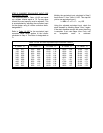
2.2 FIRING RATE ADJUSTMENT - GAS METER READINGS
2.2.1 CHECKING BURNER INPUT
The burner input rate can be checked by taking
readings from the gas meter. Please note
checking the rate with a meter is the only way to
be sure of input. Manifold readings are only an
approximate value and may vary from unit to unit.
In order to obtain accurate data, there must be no
other appliances using gas from the same meter
while the burner input rate is being checked. The
test hand on the meter should be timed for
several revolutions. The input rate in cubic feet
per hour is
calculated from this timing. The method is
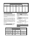
described in Lighting Instructions. If the meter is
not calibrated for gas temperature and pressure,
correction factors must be applied to determine
correct rate in SCFH (standard cubic feet per
hour). Consult the National Fuel Gas Code (ANSI
Z223.1, NFPA 54) or the local gas utility for
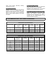
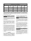
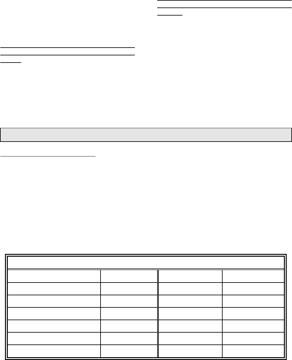
further information. Refer to Table 2.2A for
correction factors for the gas pressure at the
meter. Refer to Table 2.2B for the gas
temperature correction factors.
Table 2.2A - Pressure Correction Table 2.2B - Temperature Correction
Gas Pressure at Meter Correction Factor Gas Temp. at Meter Correction Factor
7" w.c. 1.017 40 F 0.920
14" w.c. 1.034 50 F 0.902
21" w.c. 1.051 60 F 0.885
1 psig 1.061 70 F 0.868
2 psig 1.136 80 F 0.852
5 psig 1.340 90 F 0.836