


be done with 45 elbows and not by
"bullheading" directly into the vent connector at
90 angles. "Bullhead" connections generally
cause excessive turbulence and poor draft
conditions. On vent connectors serving multiple
appliances, the diameter of the piping should be
increased at each appliance's entrance so as to
provide a relatively constant flue gas velocity
through the vent system. Using a constant
diameter breeching will often result in poor draft
at the outermost appliances.
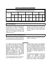
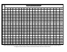
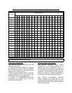
1.8.12 QUICK SELECTION FOR VENT SIZING CHARTS
GENERAL
These charts were generated using the
procedure described in Chapter 26 of the
ASHRAE Equipment Handbook (1979). The
results are consistent with those of the National
Fuel Gas Code.
The sizing herein is applicable to vent systems
utilizing double wall listed Type B vent as well as
single wall insulated
vent with insulation
equivalent to double wall insulating value.
This sizing procedure is not applicable to vent
systems utilizing single wall uninsulated vents or
vent connectors.
The sizing information given herein is intended as
a general recommendation only. Vent sizing and
installation must comply with local codes.
The responsibility for assurance of such
compliance is that of the system designer and/or
the system installer. All sizing and installation
must be checked against such local
requirements.
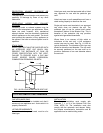
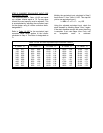
RECTANGULAR VENTS
Vent systems may be rectangular as well as
circular. Table 1.8.15F has been provided to give
the circular equivalent of rectangular duct. These
equivalent values account for the higher pressure
drop per cross section area for rectangular ducts.
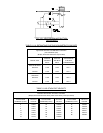
STEP 1: EQUIVALENT INPUT - DRAFT
CONTROL FACTOR
Determine the boiler (system) Draft Control
Factor, F
1
, from Table 1.8.15A.
Determine the boiler (or total system) input in
MBH. This is done by dividing the boiler (or total
system) input in Btu/hr by 1000.
Multiply the total input times factor F
1
.
The equivalent input, I, (without altitude
correction) is then:
I = MBH x F
1
eq. 15A
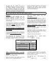
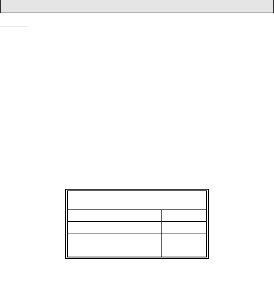
TABLE 1.8.15A: DRAFT CONTROL FACTOR F
1
Multiply factor time input in MBH
Boiler Type Factor, F
1
Atmospheric with Draft Hood 1.000
Atmospheric with Barometric 0.741
Forced Draft Gas or Oil 0.602
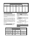
STEP 2: EQUIVALENT INPUT - ALTITUDE
FACTOR
Determine the boiler (system) Altitude Correction
Factor, F
2
, from Table 1.8.15B.
Multiply the boiler (or total system) input times
factors, F
2
and F
1
for the equivalent input.
The altitude correction factor, F
2
for atmospheric
boilers is equal to 1, because their inputs are
already derated for altitude.
The equivalent input, I, with corrections for
altitude is:
I = MBH x F
1
x F
2
eq. 15B