


OM−05463 10 SERIES
PAGE B − 2 INSTALLATION
c. Carefully read all tags, decals, and markings
on the pump assembly, and perform all duties
indicated.
d. Check levels and lubricate as necessary. Re-
fer to LUBRICATION in the MAINTENANCE
AND REPAIR section of this manual and per-
form duties as instructed.
e. If the pump and
engine have been stored for
more than 12 months, some of the compo-
nents or lubricants may have exceeded their
maximum shelf life. These must be inspected
or replaced to ensure maximum pump serv-
ice.
If the maximum shelf life has been exceeded, or if
anything appears to be abnormal, contact your
Gorman-Rupp distributor or the factory to deter-
mine the repair or updating policy. Do not put the
pump into service until appropriate action has
been taken.
POSITIONING PUMP
Use lifting and moving equipment in
good repair and with adequate capacity
to prevent injuries to personnel or dam-
age to equipment. The bail is intended
for use in lifting the pump assembly
only. Suction and discharge hoses and
piping must be removed from the pump
before lifting.
Lifting
Use lifting equipment with a capacity of at least 650
pounds (295 kg.). The pump weighs approxi-
mately 130 pounds (59 kg.) not including the
weight of accessories or suction and discharge
piping. Customer installed equipment such as suc-
tion and discharge piping must be removed before
attempting to lift.
The pump assembly can be seriously
damaged if the cables or chains used to lift
and move the unit are improperly wrapped
around the pump.
Mounting
Locate the pump in an accessible place as close as
practical to the liquid being pumped. Level mount-
ing is essential for proper operation.
The pump may have to be supported or shimmed
to provide for level operation or to eliminate vibra-
tion.
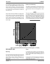
To ensure sufficient lubrication and fuel supply to
the engine, do not position the pump and engine
more than 15_ off horizontal for continuous opera-
tion. The pump and engine may be positioned up
to 30_ off horizontal for intermittent operation
only; however, the engine manufacturer should be
consulted for continuous operation at angles
greater than 15_.
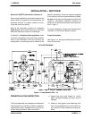
Clearance
When positioning the pump, allow a minimum
clearance of 18 inches (457 mm) in front of the
back cover to permit removal of the cover and easy
access to the pump interior.
SUCTION AND DISCHARGE PIPING
Pump performance is adversely effected by in-
creased suction lift, discharge elevation, and fric-
tion losses. See the performance curve and notes
on Page E-1 to be sure your overall application al-
lows pump to operate within the safe operation
range.
Materials
Either pipe or hose maybe used for suction and
discharge lines; however, the materials must be
compatible with the liquid being pumped. If hose is
used in suction lines, it must be the rigid-wall, rein-