


10 SERIESOM−05463
MAINTENANCE & REPAIRPAGE E − 8
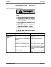
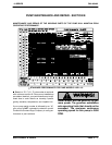
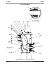
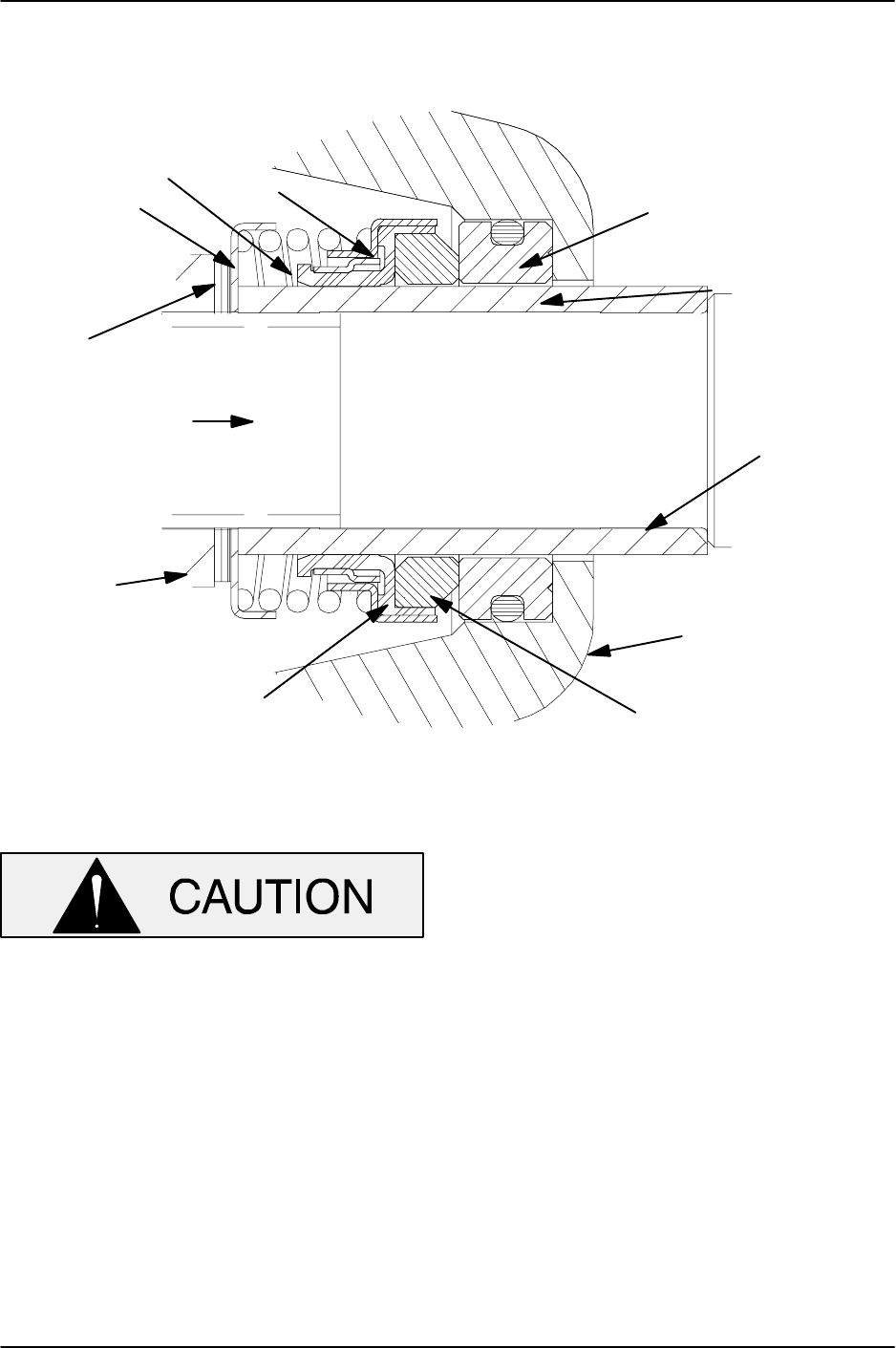
To ease installation of the seal, lubricate the O-
rings, sleeve and bellows with water or a very small
amount of oil, and apply a drop of light lubricating
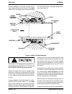
oil on the finished faces. Assemble the seal as fol-
lows, (see Figure 3).
SPRING
CENTERING
WASHER
SPRING
RETAINER
O-RING
STATIONARY
SEAT
SHAFT
SLEEVE
INTERMEDIATE
ROTATING
ELEMENT
BELLOWS
IMPELLER
ENGINE STUB
SHAFT
IMPELLER
SHIMS
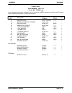
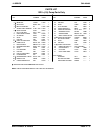
Figure 3. 25285−855 Seal Assembly
This seal is not designed for operation at
temperatures above 160_F (71_C). Do not
use at higher operating temperatures.
Inspect the engine stub shaft for damage. Small
scratches or nicks may be removed with a fine file
or emery cloth. If the stub shaft is bent of excessive-
ly worn, replace the shaft (see the engine service
manual).
To ease installation of the intermediate O-ring (21),
lubricate the O-ring with water or a very small
amount of oil. Install the O-ring on the intermediate.
Position the intermediate against the engine bell-
housing and secure it with hardware (19 and 20).
Assemble the O-ring into the stationary seat. Press
the stationary seat into the intermediate bore until
fully seated. A push tube cut from a length of plastic
pipe would aid this installation. The I.D. of the tube
should be approximately the same as the I.D. of the
seal spring.
Subassemble the rotating element into the retainer
and bellows. Apply a drop of light oil on the preci-
sion finished faces; never use grease. Use even
pressure to carefully press this subassembly onto
the sleeve (6) until the rotating element is just flush
with the chamfered end of the sleeve.
Slide the sleeve and assembled rotating portion of
the seal onto the shaft until the seal faces contact.
Continue to push the sleeve through the seal until it
seats squarely against the shaft shoulder.
Install the seal spring and spring centering washer.