


OM−0546310 SERIES
MAINTENANCE & REPAIR PAGE E − 9
Lubricate the seal as indicated in LUBRICATION,
after the impeller has been installed.
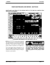
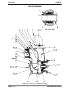
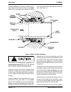
Impeller Installation And Adjustment
(Figure 2)
Inspect the impeller and replace it if cracked or
badly worn. Install the same thickness of impeller
shims (4) as previously removed. Apply anti-seize
to the shaft threads and screw the impeller onto the
shaft until tight.
A clearance of .008 to .015 inch (0,20 to 0,38 mm)
between the impeller and the intermediate is nec-
essary for maximum pump efficiency. Measure this
clearance and add or remove impeller shims until
this clearance is reached.
Pump Casing Installation
(Figure 2)
Secure the pump casing (1) to the intermediate
with the hardware (17 and 18). Be careful not to
damage the O-ring.
See Figure 1 and secure the pump casing to the
base (3) with the hardware (12, 13 and 14). Be sure
to reinstall any leveling shims used under the
mounting feet of the pump casing.
Back Cover Installation
(Figure 2)
Inspect the wear plate (22) and replace it if badly
worn or grooved. Install the wear plate on the back
cover using the hardware (24 and 25).
Clean any scale or debris from the back cover
shoulder and pump casing which might prevent a
good seal.
NOTE
Apply a film of ‘Never-Seez’ or equivalent com-
pound on the back cover shoulder or any surface
which contacts the pump casing to ease future dis-
assembly and to reduce rust and scale build up.
Replace the back cover gasket (33) and slide the
back cover assembly (29) into the pump casing.
Be sure the wear plate does not scrape against the
impeller.
Secure the back cover assembly to the pump cas-
ing using the hardware (27 and 28). Do not over
tighten the wing nuts; they should be just tight
enough to ensure a good seal at the back cover
shoulder.
Suction Check Valve Installation
(Figure 2)
Inspect the check valve components and replace if
required.
Position the check valve assembly (37) in the suc-
tion port with the check valve plate (40) facing to-
ward the inside of the pump casing. Install the suc-
tion flange (34) and secure with the nuts (36).
Check the operation of the check valve to ensure
proper seating and free movement.
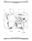
Final Pump Assembly
(Figure 1)
Be sure the pump and engine are securely
mounted to the base.
Install the suction and discharge lines and open all
valves. Make certain that all piping connections are
tight, properly supported and secure.
Be sure the engine has been properly lubricated,
see LUBRICATION.
Remove the fill plug assembly (7). Fill the pump
casing with clean liquid. Reinstall the fill plug and
tighten it.
Refer to OPERATION, Section C, before putting
the pump back into service.
LUBRICATION
Seal Assembly
(Figure 2)
The seal assembly is lubricated by the medium be-
ing pumped. No additional lubrication is required.
Engine
Consult the literature supplied with the engine, or
contact your local Honda engine representative.