


Page 48
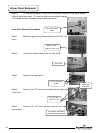
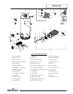
inner door gasket to the inner door sections. Refer to the illustration for proper applica-
tion. Note the overlap configuration in the flange area of the inner door. Set the flange
section first, and this will help to achieve the proper overlap position.
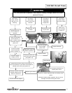
Inner Door Installation with Gasket
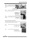
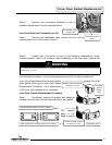
Step 1. Clean any residual gasket residue or other debris from the combustion
chamber surface before installing the inner door/gasket assembly.
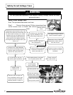
Step 2. Place the left side inner door into position first, being sure to firmly posi-
tion the concave channel of the inner door around the feedline.
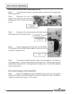
Step 3. Using the 1/4” hex drive screws removed in Step 5 of the Inner Door Re-
moval Procedure on page 32, secure the left side inner door in place. Do not over-
tighten the screws.
Step 3. Position the pilot tube and spark igniter wire against the left side inner
door flange gasket. Do not route these through the concave channel with the feedline.
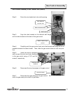
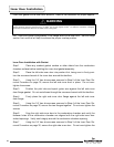
Step 4. Firmly place the right side inner door flange against the left side inner
door flange.
Step 5. Using the 1/4” hex drive screws removed in Step 4 of the Inner Door Re-
moval Procedure on page 32, secure the two flanges together. Do not over-tighten the
screws.
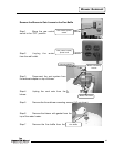
Step 6. Align the right side inner door to the combustion chamber and verify the
fastener holes of the combustion chamber are aligned with the right side inner door
slotted openings. Verify seal integrity around the combustion chamber opening.
Step 7. Using the 1/4” hex drive screws removed in Step 3 of the Inner Door Re-
moval Procedure on page 32, secure the right side inner door. Do not over-tighten the
Inner Door Installation
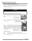
WARNING
Stripped fastener connections may allow for an inner door seal breach. A seal breach may result in a fire or explosion,
causing property damage, personal injury, or death. Do not over tighten screws. If a fastener connection is stripped,
contact the manufacturer listed on the water heater rating plate.
48