


Page 33
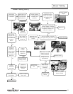
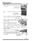
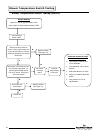
Blower Temperature Switch Replacement
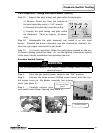
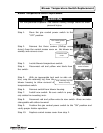
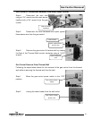
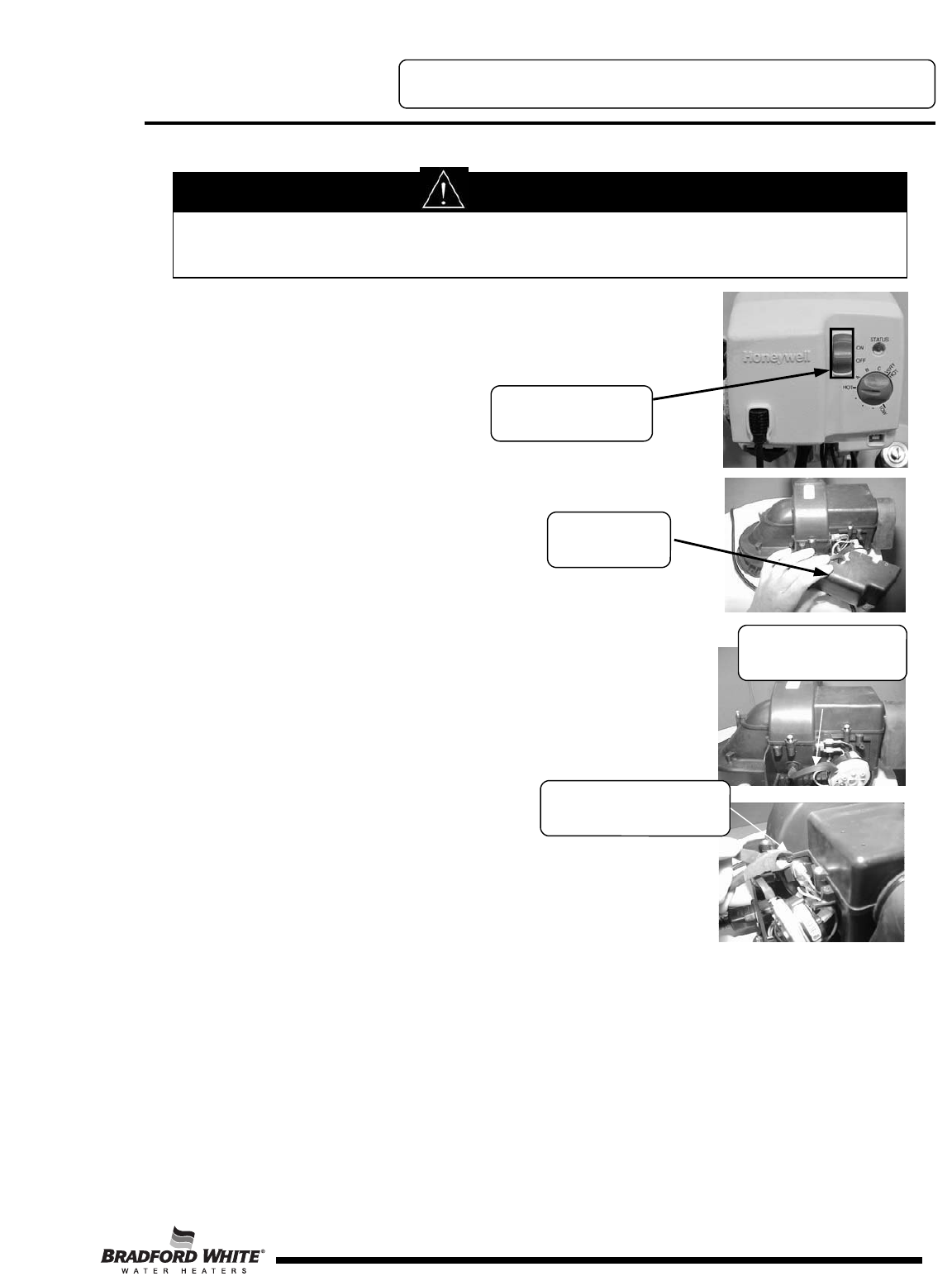
Step 1. Move the gas control power switch to the
“OFF” position.
Step 2. Remove the three screws (Phillips screw
driver) from the control access cover on the blower as-
sembly and remove cover.
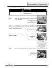
Step 3. Locate blower temperature switch.
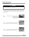
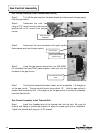
Step 4. Disconnect red and yellow wire leads from
the switch.
Step 5. With an appropriate tool such as side cut-
ters, snip the retaining lug from the
blower housing to allow removal of
temperature switch.
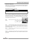
Step 6. Remove switch from blower housing.
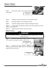
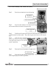
Step 7. Install new switch. Be sure switch is prop-
erly seated in mounting area.
Step 8. Reconnect red and yellow wires to new switch. Wires are inter-
changeable with either terminal.
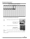
Step 9. Position the gas control power switch to the “ON” position and
verify proper heater operation.
Step 10. Replace control access cover from step 2.
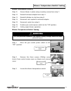
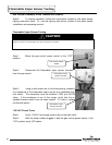
WARNING
115 volt potential exposure. Use caution making voltage checks to avoid
personal injury.
Gas control power
switch
Control access
cover
Blower temperature
switch location
Snip retaining lug from
blower housing
Blower Temperature Switch Replacement
33