


Page 21
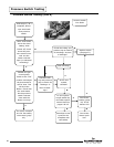
Burner Cleaning Procedure (cont’d)
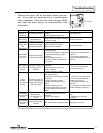
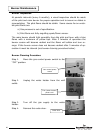
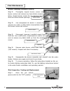
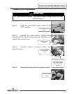
Step 5. Remove the (4) 1/4” hex drive screws holding
the right side inner door in place.
Step 6. Remove the (3) 1/4” hex drive screws holding
the left side burner door in place.
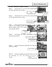
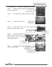
Step 7. Disconnect the pilot tube
using a 7/16” wrench and the main
burner feedline with a 3/4” wrench
from the gas control.
Step 8. Disconnect the spark igniter/flame sensor
wire from gas control.
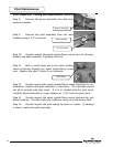
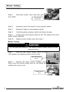
Step 9. Remove the burner assembly from the com-
bustion chamber.
Step 10. Remove manifold mount from burner inner door
by removing (2) 1/4” hex drive
screws.
Burner Maintenance
(4) 1/4” hex drive
screws
Pilot and main
feedlines
Spark igniter/flame
sensor wire
Gas control
Burner assembly
Right side
inner door
(3) 1/4” hex
drive screws
Left side
burner door
(2) 1/4” hex drive
screws
21