


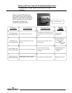

SERVICE PROCEDURE I
Inner Door/Gasket Removal, Inspection
Replacement and Reinstallation
8
The Bradford White
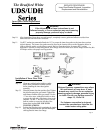
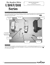
Step 15. Firmly place right side inner door flange against the burner door flange and secure with two ¼” drive
screws from step 5. DO NOT OVER TIGHTEN SCREWS.
Step 16. Align right side inner door to combustion chamber and verify the fastener holes of the combustion
chamber are aligned with the right side inner door slotted opening. Verify seal integrity around combustion
opening. Secure right side inner door using 1/4” hex drive screws from step 5. DO NOT OVER TIGHTEN
SCREWS. Verify both burner and right sides of the inner door are properly positioned and sealed against
the combustion chamber.
Step 17. Reconnect the igniter wire to the gas control
Step 18. Replace outer jacket burner access door.
Step 19. To resume operation follow the instructions located on the lighting instruction label or the lighting instructions
located in the installation and operation manual.
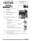
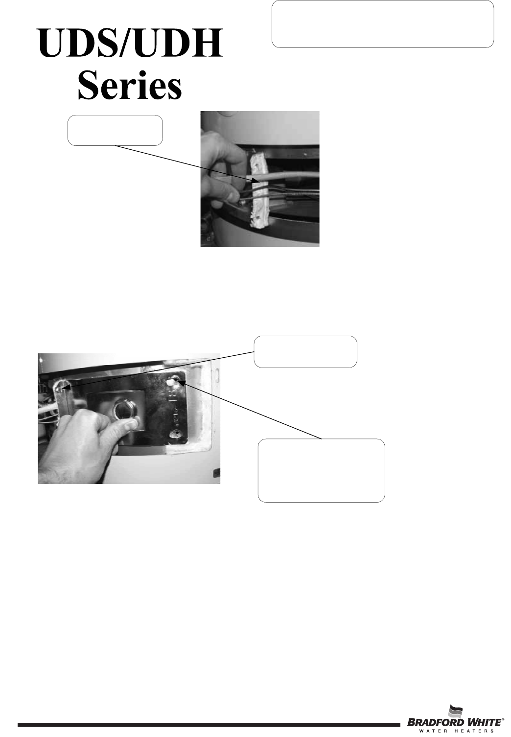
Verify threaded hole
alignment with slotted
openings in inner door.
Position fiberglass sock, pilot
tube and armored thermopile
cable against flange.
Secure flange with
¼" drive screws.
8