


13
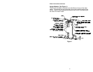
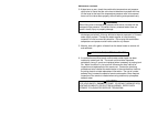
Electrical Connections
Before any electrical connections are made, be sure that the water heater is
full of water and that the manual shut-off valve in the cold water supply line is
open. Check the rating plate and wiring diagram before proceeding. This
electric water heater was built and wired in accordance with the Underwriters
Laboratories testing approvals requirements. The temperature limiting
device is of the manual reset, trip-free type and has been factory installed to
interrupt all ungrounded power supply conductors in the event of thermostat
failure. Thermostats are factory set and wired in accordance with the wiring
diagram fastened to the inside of the top access panel. The plumbing
supplier in your area ordered this heater wired at the factory to comply with
existing area codes, but local utility codes may require or allow other
circuitry. Consult your local power company to determine the correct
electrical hook-up in order to meet local utility and building codes and in
order to obtain the most economical rates. Also check to find out if you are
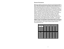
required to obtain a permit before starting the installation. The following
chart shows the recommended fuse size for the maximum water heater
wattage. The maximum wattage and rated voltage are shown on the water
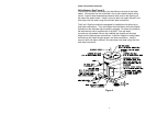
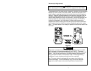
heater data plate. The water heater must be well grounded. A green ground
screw is provided at the electrical connection point for connecting a ground
wire. Ground screw on 10 & 15-gallon models is located under the
removable element cover.
Recommended Fuse size
Voltage
Max. Watts 120v 208v 240v 277v 480v
1000 15A 10A 10A 10A 10A
1250 15A 10A 10A 10A 10A
1500 20A 10A 10A 10A 10A
2000 25A 15A 15A 10A 10A
2500 30A 15A 15A 15A 10A
3000 35A 20A 20A 15A 10A
3500 --- 25A 20A 20A 10A
4000 --- 25A 25A 20A 15A
4500 --- 30A 25A 25A 15A
5000 --- 30A 30A 25A 15A
5500 --- 35A 35A 25A 15A
6000 --- 40A 35A 30A 20A