


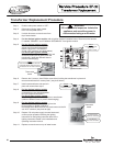

Transformer Replacement Procedure
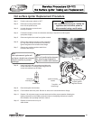
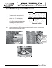
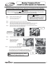
Step 4. For Hot Surface Ignition models, refer to ignition module illustration below, Disconnect wire harness
P1 labeled “PRIMARY” and P2 labeled “SECONDARY” from ignition module.
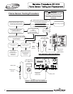
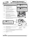
Step 5. For Hot Surface Ignition models,
Disconnect secondary leads (blue &
yellow wire) from thermostat board.
Note the blue wire is connected to
24 volt “HOT” terminal. (see photo below)
For Direct Spark Ignition models,
Disconnect primary leads (black & white) and
secondary leads (blue & yellow) from the
transformer. (leads are different sizes to
prevent interchanging)
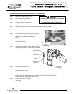
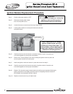
Step 6. Remove the 2 screws ( short Phillips screw driver) holding the transformer in place and
remove transformer from control panel. (see photo below)
Step 7. Install new transformer and secure in
place with screws from step 6.
Step 8. For Hot Surface Ignition models,
Reconnect wire harness P1 & P2,
connections are non-interchangeable
to insure proper reconnection.
For Direct Spark Ignition models,
Reconnect primary and secondary wires to transformer.
(leads are different sizes to prevent interchanging)
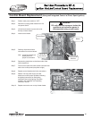
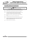
Step 9. For Hot Surface Ignition models,
Reconnect blue & yellow wire leading from the
P2 connection on ignition module to
thermostat board. Note the blue wire must connect to the 24
volt “HOT” terminal. (see photo at right)
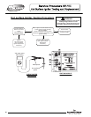
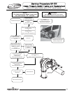
Step 1. Position main power switch to “OFF”.
Step 2. Disconnect (Unplug) water heater
f
rom 120 Volt power source.
Step 3. Un-latch & remove surround cover from
top of water heater.
Step 10. Restore 120 volt power supply to water heater and
confirm proper operation following the lighting
instructions on the lighting instruction label or the
lighting instruction located in the installation and
operating instruction manual.
Step 11. Replace surround cover on top of water heater.
WARNING
120 volt potential exposure. Isolate the
appliance and reconfirm power is
disconnected using a multi-meter.
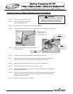
Step 3
Disconnect harness
“P1” & “P2”
from ignition module
Ignition module
Step 5
Disconnect blue & yellow wire from
thermostat board. Note blue wire is
connected to 24 volt “HOT” terminal.
Thermostat
board
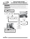
Step 6
Remove transformer
mounting screws
24 volt common,
yellow wire connection
24 volt Hot,
blue wire connection
Thermostat
board
68
68