


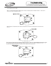
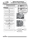
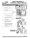
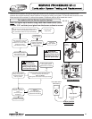
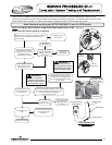

Refer to ignition module
illustration, Is there 120VAC
between P1(1) and P1(3)?
Refer to ignition module
illustration, Is there
22 - 27VAC between
P2(1) and P2(2)?
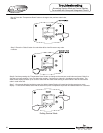
Refer to ignition module
illustration, Is there 120VAC
between P7(3) and P7(1)?
Replace transformer.
(see Transformer
Replacement)
Refer to ignition module
illustration, Is there 24VAC
between P3(9) and P2(1).
N
N
Y
Y
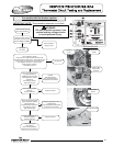
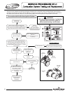
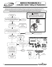
Check wire harness
continuity. Replace
thermostat sensor or wire
harness as necessary.
(see “Thermostat Sensor
Replacement Procedure”)
Check AC source to
determine why there is no
power.
Replace
ignition module.
(see “Ignition Module
Replacement”)
N
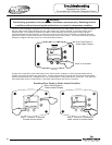
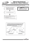
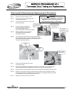
Check continuity through
ECO, red wires of
thermostat sensor.
Check at temperature
less than 160°F
Is there continuity?
(see photo at right)
N
Replace ignition module.
(see “Ignition Module
Replacement”)
Y
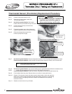
Replace thermostat
circuit board.
(see “Thermostat Board
Replacement Procedure”)
Y
N
Y
IGNITION MODULE
Thermostat circuit.
(continued from page 37)
WARNING
120 volt potential exposure. Use caution
making voltage checks to avoid personal injury.
For models with Hot Surface Ignition
39
Red Wires
(Temperature Sensor)
39