


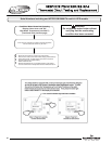
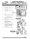
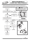
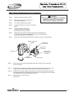
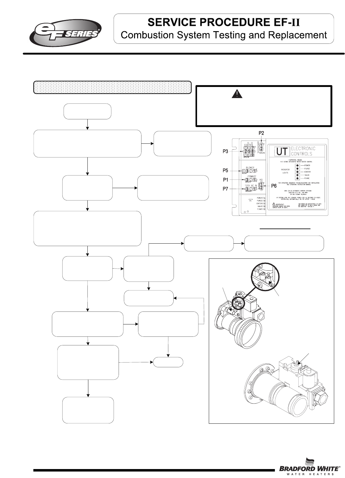
Refer to ignition module illustration below,
is there 24VAC between P3(2) and P3(5) (blue and
brown wires) during the flame establishing period?
(Note: Valve LED must be lit during this check)
Y
Replace
ignition module.
(see “Ignition Module
Replacement Procedure”)
N
Replace Rectifier harness and/or
gas valve.
(see “Gas Valve Replacement
P
rocedure”)
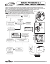
N
Y
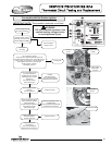
Does flame LED on the module
light and stay lit?
Can you hear or feel
gas valve energize?
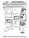
Does burner light
smoothly, without
evidence of coughing
or huffing?
Y
N
Check for obstruction
at inlet of gas valve.
Is inlet free of
obstruction?
Check flame sensor,
Is there 1 to 5 micro amps
(min.) during 1.5 second
flame proving period?
(see “Flame Sensor Testing
Procedure”)
N
Y
IGNITION MODULE
Continued from
previous page
N
Call for technical
support
Clear obstruction
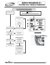
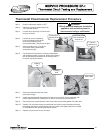
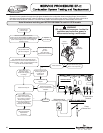
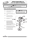
Observe burner operation through the sight glass located on the combustion insert mounting flange. Normal burner
o
peration should ignite smoothly, without evidence of coughing or huffing upon ignition. The burner flame should be a
blue flame near the burner surface in a uniform flame pattern. Occasional yellow or white streaks are normal.
Y
Does burner operate
normaly until thermostat is
satisfied?
N
System OK
Y
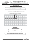
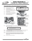
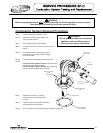
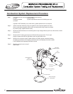
Turn VENTURI set screw clockwise until its
bottomed out. Turn screw counter-clockwise 6-½
turns from bottom (see illustration below). Note:
EF100T399 models do not have a venturi screw.
The gas regulator setting should be 1 - 1 ¼ turns
out from bottom.
Replace flame sensor
(see “Flame Sensor
Replacement
Procedure”)
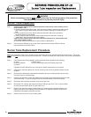
Inspect burner tube, (see “Burner
Tube Inspection and Replacement”)
N
Y
N
WARNING
120 volt potential exposure. Isolate the
appliance and reconfirm power is
disconnected using a multi-meter.
Y
Venturi
adjustment
Inlet gas
pressure tap
EF100T399
Only
Gas valve
regulator
44
For models with Hot Surface Ignition System
44