


SERVICE PROCEDURE D24-II
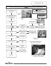
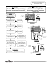
Pilot Operation Testing
CAUTION
Be Careful When Making Voltage
Measurements or Jumping Terminals
Not to Damage or Deform Connectors or
Connector Pins.
DANGER
120 volt exposure. To avoid personal injury,
use caution while performing this procedure.
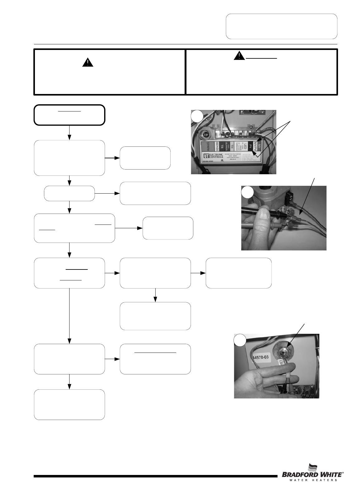
Condition:
Pilot will not light,
Ignition module LED is “ON”
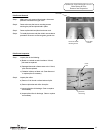
Is there 22-27 volts AC output across
terminals “MV/PV” & “PV” of Ignition
Module? Disconnect wires & check
across terminal of module.
(see photo 11)
N
Y
Loosen pilot tubing connection at
the gas valve and soap test.
Is there pilot gas flow out of the
gas valve?
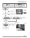
Tighten pilot tube connection at
the gas valve. Check incoming
gas pressure to water heater. if
okay, replace gas valve
Check for clogged or kinked
pilot tube, clogged pilot orifice.
Clean or replace as needed.
(see page 13)
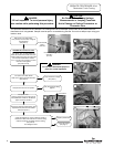
Is there 22-27 volts AC input
across wire leads
“MV/PV” & “PV”
at Gas Valve?
(see photo 12)
Check continuity across ECO
(RED) leads of lower thermister
(see photo 13)
Is continuity okay?
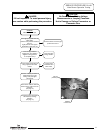
Check wire harness for damage
or loose connections. Repair or
replace as needed.
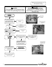
R
eset heater by turning power
“
OFF”. Wait 5 seconds and turn
power “ON”. When LED of
i
gnition module turns “ON” does
i
gnition module send “spartk”
s
ignal (buzzing or clicking sound)
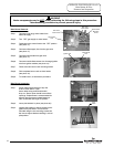
11
Replace ignition
module
12
Check across
“MV/PV” & “PV”
terminals
C
heck across “MV/PV”
&
“PV” Wire leads to
g
as valve
13
Check across RED
wire leads of lower
thermister (ECO).
ECO Specifications
Opens between 181°F/201°F
Closes between 160°F/100°F
N
Y
YY
NN
Y
N
Replace ignition
module
Is there spark at the
pilot?
Check for:
Loose or damaged ignition wire
Grounded pilot electrode
Damaged pilot.
Y
N
Page 8
8