


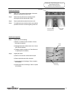
1
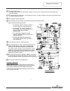
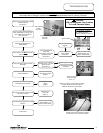
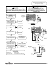
Thermostat calls for heat.
The relay closes on the thermostat board, sending 24 volts from the “COM” terminal of the thermostat board
to the flue damper.
2
Flue damper begins to rotate open. Once damper is full open, 24 volts is allowed to continue through damper to the
“
TH” terminal of ignition module.
3
LED on ignition module illuminates.
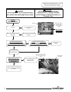
4
5
Once pilot flame is proven, sparking will stop.
Page 4
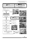
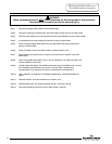
Sequence of Operation
Trial for ignition (90 second trials, 3 trials with 30 second pause between trials).
Ignition module simultaneously sends:
1. 24 volts from “MV/PV” terminal, to “MV/PV”
terminal of gas valve (common terminal).
2. 24 volts from “PV” terminal, through the
ECO located in the lower thermister, to “PV”
terminal of gas valve to establish
gas flow at pilot.
3. Low current high voltage from “spark”
terminal, to generate spark at the pilot and
ignite pilot gas flow.
4. Pilot flame proving signal (measured in
micro-amps). from the “sense” terminal, to
prove pilot flame.
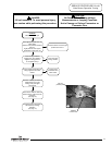
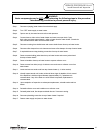
6
Once sparking stops, 24 volts is sent from “MV” terminal on
module, to “MV” terminal on gas valve to establish main
burner gas flow. Main burners ignite from the pilot flame.
The ignition module constantly monitors pilot flame. If pilot
flame is lost, pilot and main burner are shut down. After a
30 second purge period, module will attempt to re-light pilot
beginning at sequence 4 above.
7
Main burner fires until the thermostat is satisfied. The relay on
the thermostat board opens, interrupting 24 volts through the
damper and ignition module. Pilot and main burner is turned off.
8
Flue damper rotates to the closed position.
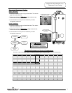
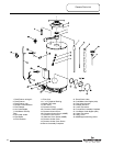
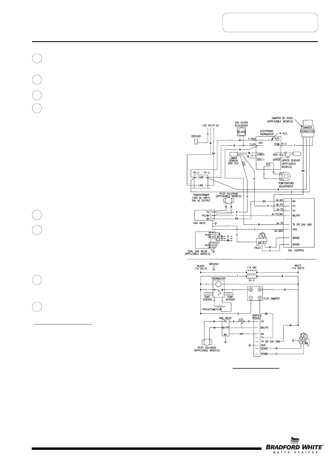
WIRING DIAGRAM
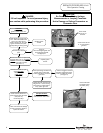
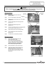
LOCKOUT CONDITION
Ignition module will “lockout” if the pilot can not be lit after 3
ignition trials. The ignition module indicates a lockout condition
by the continues flash of the LED located on the module.
Lockout reset is accomplished by interrupting 120 VAC to the
unit for at least 5 seconds.
4