


SERVICE PROCEDURE D24-I
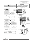
Thermostat Circuit Testing
CAUTION
Be Careful When Making Voltage
Measurements or Jumping Terminals
Not to Damage or Deform Connectors or
Connector Pins.
DANGER
120 volt exposure. To avoid personal injury,
use caution while performing this procedure.
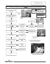
T
HERMOSTAT CIRCUIT BY-PASS
T
urn power “OFF” to water heater and
locate thermostat board inside control box
of water heater. Disconnect YELLOW wires
from the thermostat board at location
“N.O.” & “COM”. Use a jumper to connect
these two wires together
(see photos 4 & 5).
Does pilot and main burner operate?
3
5
W
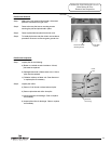
ith power on to water heater,
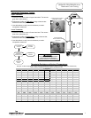
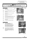
Verify Primary and secondary voltage at
the transformer
(see photo 3)
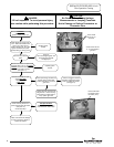
Turn power on to water heater.
Does LED on ignition module illuminate?
(see photo 6)
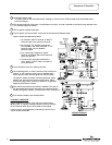
T
his procedure assumes the flue damper is in working order. Be sure damper opens under its own power when the
thermostat circuit is by-passed. Damper must be open or removed during this test. Do not force damper open using your
hands or tools.
Y
N
Y
N
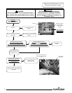
Verify transformer voltage
(see photo 3)
See pilot operation testing
(page 8)
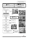
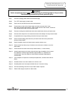
Disconnect ORANGE potentiometer (temp
adjustment dial) wires from thermostat
board (see photo 7)
DANGER
Do not leave thermostat jumper in
place for normal operation.
Turn power “OFF”.
Remove jumper and re-connect wires to
thermostat board. Wires are identified for
proper connection to board.
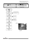
Check potentiometer for proper resistance values of:
Greater then 4800 Ohms with dial at minimum setting.
Less than 50 Ohms with dial at maximum setting.
(see photo 8).
Are readings correct?
Replace potentiometer
Check Thermisters
(see page 7)
Y
N
7
8
4
Rear terminals
primary
(120 VAC)
Forward terminals
secondary
(24 VAC)
6
LED Location
Page 6
6