


SERVICE PROCEDURE AG-III
Combination Thermostat/Gas Valve
Testing and Replacement
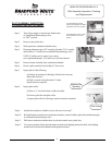
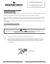
Step 7. Removal of combination thermostat/gas valve.
a) Disconnect main burner feedline (¾” wrench), pilot tube (7/16" wrench) and thermocouple (3/8" wrench)
from combination thermostat/gas valve & remove burner from combustion chamber.
NOTE: Feed line nut for natural gas control uses right hand threads,
LP control uses left hand thread.
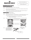
b) Remove Combination Thermostat/Gas Valve from heater,
rotating counter clockwise using a control body wrench or a
length of ½" NPT pipe threaded into inlet of control.
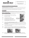
Step 8. Installation of Combination Thermostat/Gas Valve.
a) Install new combination thermostat/gas valve using a control body wrench or a length of ½" NPT
pipe threaded into inlet of control. DO NOT OVER TIGHTEN. Use caution not to damage cast
aluminum body of combination thermostat/gas valve. Be certain not to damage the bundled wire
leads.
NOTE: Combination thermostat/gas Valve must be installed in proper upright position to
assure the feedline will align properly at the inner door flange.
DO NOT OVER TIGHTEN. If control is turned past proper alignment, do not
reverse direction to align.
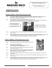
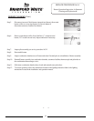
b) Reattach main burner feedline, pilot tube and thermocouple to combination thermostat/gas valve.
NOTE: Feedline nut for natural gas control uses right hand threads,
LP control uses left hand thread.
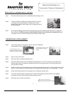
c) Connect gas supply piping to inlet of control. Use back up wrench on wrench boss of control, never
use back up wrench on body of control.
Page 9
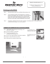
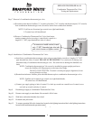
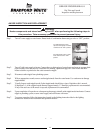
To remove or install control, insert
only ½" NPT threaded pipe into inlet
and use to loosen or tighten control.
Wrench Boss
Step 9. Reconnect gas supply to Combination Thermostat/Gas Valve.
Step 10. Resume water supply to water heater. Be sure tank is full of water.
Step 11. Slide inner combustion chamber door closed
Step 12. Re-attach outer jacket door.
Step 13. To resume operation follow the instructions located on the lighting instruction label or the lighting instructions
located in the installation and operation manual.
9